What do the numbers on a cordless drill represent. How can you adjust the torque control on a drill. What are the different symbols on a cordless drill and their meanings.
Decoding the Numbers on Cordless Drills
Cordless drills are versatile tools that come with various numbers and symbols, often leaving users puzzled about their meanings. Let’s dive into the significance of these markings and how they can enhance your drilling experience.
Torque Control Numbers
The most prominent numbers on a cordless drill are typically found on the torque adjustment ring near the chuck. These numbers represent the torque settings, which control the amount of rotational force applied by the drill. The range usually spans from 1 to 20 or higher, depending on the model and manufacturer.
- Lower numbers (1-5): Ideal for delicate tasks and small screws
- Middle numbers (6-15): Suitable for general-purpose drilling and driving
- Higher numbers (16+): Best for heavy-duty tasks and larger fasteners
How does torque control benefit your drilling tasks? By adjusting the torque, you can prevent over-tightening screws or stripping screw heads. This feature is particularly useful when working with different materials or screw sizes.
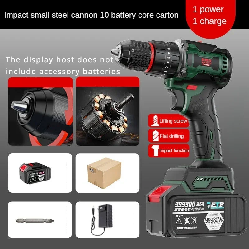
Mastering Torque Adjustment on Your Cordless Drill
Adjusting the torque on your cordless drill is a simple process that can greatly improve your drilling precision. Here’s a step-by-step guide to help you master this essential skill:
- Locate the torque adjustment ring near the chuck
- Identify the arrow indicating the current torque setting
- Rotate the ring clockwise to increase torque, counterclockwise to decrease
- Start with the lowest setting and test on scrap material
- Gradually increase the torque until you achieve the desired result
- Fine-tune the setting based on the specific task and material
Why is it important to practice adjusting torque settings? Familiarizing yourself with your drill’s torque capabilities allows you to work more efficiently and prevents damage to both your workpiece and the tool itself.
Gear Selection Settings: Unlocking Your Drill’s Full Potential
Many cordless drills feature multiple gear settings, typically represented by numbers (1, 2, or 3) on a separate selector switch. These gears control the drill’s speed and power output, allowing you to optimize performance for different tasks.
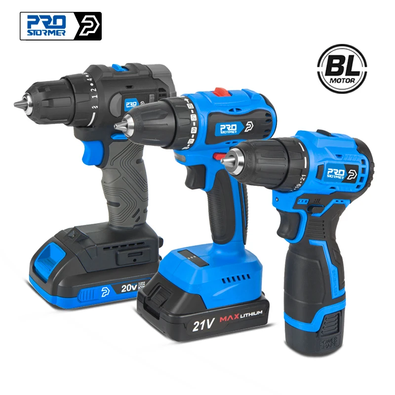
- Gear 1: High torque, low speed – ideal for driving large screws or drilling into dense materials
- Gear 2: Medium torque, medium speed – suitable for general-purpose drilling and driving
- Gear 3 (if available): Low torque, high speed – perfect for quick drilling in softer materials
How can you effectively use gear selection to improve your drilling experience? By matching the gear to your task, you can achieve better control, reduce battery drain, and extend the life of your drill bits and fasteners.
Deciphering Drill Mode Symbols: A Visual Guide
Modern cordless drills often come equipped with multiple operating modes, each represented by a unique symbol. Understanding these symbols is crucial for maximizing your drill’s versatility.
Drilling Mode
The drilling mode symbol typically resembles a drill bit or a spiral. This setting is used for standard drilling operations in various materials.
Driving Mode
The driving mode symbol often looks like a screw. This setting is optimized for driving screws and other fasteners, utilizing the drill’s torque control feature.
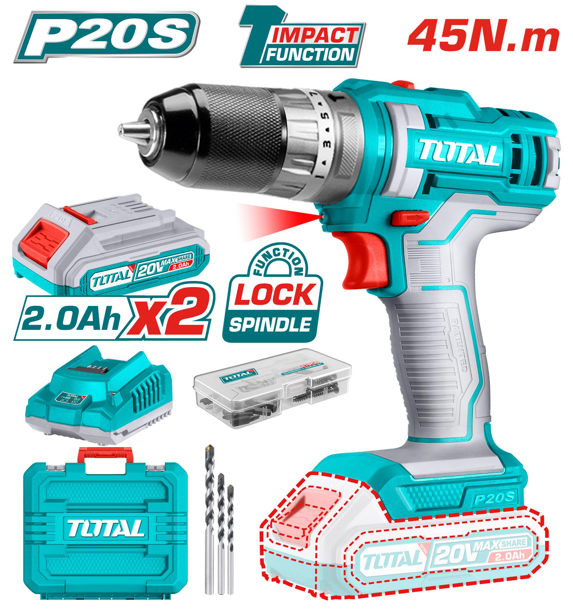
Hammer Drill Mode
The hammer drill mode symbol usually depicts a hammer or a drill bit with wavy lines. This mode adds a percussive action to the rotation, making it ideal for drilling into masonry or concrete.
Why is it essential to use the correct mode for each task? Selecting the appropriate mode ensures optimal performance, reduces wear on your drill and accessories, and helps achieve the best results in your projects.
Choosing the Right Torque Setting for Different Materials
Selecting the appropriate torque setting is crucial for efficient and damage-free drilling or driving. Here’s a general guide to help you choose the right torque for common materials:
- Softwoods: Low to medium torque (5-10)
- Hardwoods: Medium to high torque (10-15)
- Drywall: Low torque (1-5)
- Plastic: Low to medium torque (5-10)
- Metal: Medium to high torque (10-20)
- Masonry (with hammer function): Highest torque setting
How can adjusting torque for different materials improve your work quality? By using the appropriate torque setting, you can prevent over-driving screws, reduce material damage, and ensure a clean, professional finish on your projects.
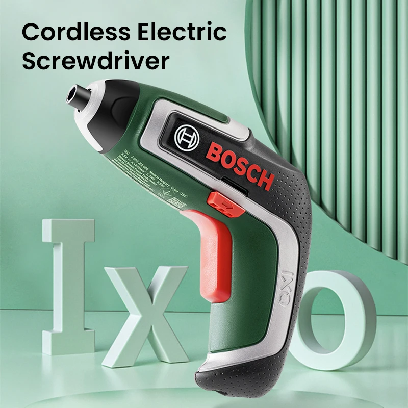
Maximizing Battery Life Through Proper Drill Settings
Optimizing your cordless drill’s settings not only improves performance but can also significantly extend battery life. Consider these tips to get the most out of your drill’s battery:
- Use lower gear settings for tasks that don’t require high speed
- Avoid using maximum torque settings unless necessary
- Utilize the drill’s clutch to prevent overworking the motor
- Switch to manual tools for simple tasks to conserve battery power
- Keep batteries warm in cold conditions to maintain efficiency
Why is battery management crucial for cordless drill users? Proper battery care and usage can extend the life of your batteries, reduce downtime on the job, and save money on replacements in the long run.
Advanced Features: Beyond Basic Drill Functions
As cordless drill technology advances, manufacturers are incorporating additional features to enhance functionality and user experience. Some advanced features you might encounter include:
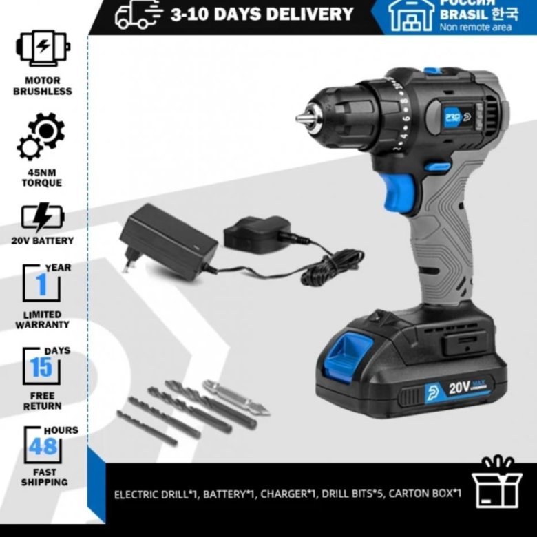
- Brushless motors for increased efficiency and longevity
- Electronic clutches for precise torque control
- Built-in LED work lights for improved visibility
- Smart connectivity for tool tracking and customization
- Automatic bit detection for optimal speed and torque settings
How can these advanced features benefit your drilling tasks? By leveraging these technologies, you can achieve greater precision, work more efficiently in various conditions, and extend the lifespan of your tools.
Maintaining Your Cordless Drill for Optimal Performance
Proper maintenance is essential for keeping your cordless drill in top condition and ensuring it operates at peak performance. Follow these maintenance tips to extend the life of your tool:
- Clean the drill regularly, removing dust and debris
- Lubricate moving parts according to the manufacturer’s instructions
- Inspect and replace worn chuck jaws or collets
- Store the drill in a dry, cool place when not in use
- Avoid dropping or mishandling the tool to prevent internal damage
- Use only compatible batteries and chargers
Why is regular maintenance crucial for cordless drill owners? By keeping your drill in good condition, you can ensure consistent performance, reduce the risk of malfunctions, and avoid costly repairs or replacements.
Understanding the numbers and symbols on your cordless drill is key to unlocking its full potential. By mastering torque control, gear selection, and mode settings, you can tackle a wide range of drilling and driving tasks with precision and efficiency. Remember to choose the right settings for your materials, optimize battery usage, and maintain your tool regularly to ensure years of reliable service. With these insights, you’ll be well-equipped to make the most of your cordless drill in all your DIY and professional projects.
What Do The Numbers And Symbols On Cordless Drills Mean
When you use a cordless drill, perhaps you’ve noticed a dial near the drill head with different numbers or symbols on it. If you have, you’ve probably wondered to yourself, “what are the different numbers/symbols on a cordless drill and what do they mean?”
The numbers on a cordless drill indicate the torque breaking point or rotary power. The higher the number, the greater the force or torque. This feature is very useful. It not only allows you to adjust the amount of turning power applied to prevent screws from being stripped, but it also provides the ability to bore holes in hard materials such as wood, concrete, masonry, and metal.
Now that you know what the numbers on a cordless drill mean, let’s take a closer look at this in more detail below.
We’ll explain how to adjust the torque or clutch settings on a drill and what the hammer settings on a cordless drill do. We’ll also give you some information on a great cordless drill with the highest torque capacity.
So, if you’re ready to learn more about cordless drill numbers and/or symbols, then let’s get started!
* This article may contain affiliate links. As an Amazon Associate, I earn from qualifying purchases.
What Do the Numbers Represent on a Drill?
On most modern drills you can find two areas with numbers. One is the gear selection and the other the torque control.
How Do You Change Drill Torque Control?
As mentioned at the beginning of the article, the numbers on a drill represent the amount of torque the tool can apply to an object (such as a screw) or for hole drilling. The numbers usually range from 1 to 20 (or more) with 1 representing the least amount of torque and 20, the greatest.
Some drills can have a range of over 20. It depends on the manufacturer and drill model.
To adjust the torque control on a drill, follow these 6 simple steps:
- Find the torque adjustment ring or dial.
 It’s usually located on the ‘head’ of the tool near the drill bit, which is the part that spins. This area is also referred to as a chuck.
 - Locate the arrow on top of the tool. It will point to a number indicating which torque setting is to be used. The higher the number, the greater the torque!
- Adjust the torque by turning the ring, clockwise for more power or counter-clockwise for less.
- Begin by testing the drill first. Choose the lowest setting or number (typically 1). Grab a piece of practice wood and drill into it to get a ‘feel’ for the tool. Don’t forget the safety equipment and secure the wood in place.
- Next, turn the dial to the middle (if the drill has numbers from 1 to 20, then choose 10) and once again, test out the drill’s power on the same piece of practice wood.
- Finally, turn the ring to the highest torque setting (likely, 20 or more) and drill the screw into the practice wood a third time. This will demonstrate the power or the tool and how fast it can go!
It’s very important to test a drill out before you use it on your next woodworking project.
You need to be aware of how much power the tool has and how it will react and/or handle.
Too much torque can be hard to handle and it will strip screws, whereas too little can be tedious.
Over time, you’ll get a ‘feel’ for how the drill handles. The more you use it and test its capabilities, the easier it’ll be for you to choose which torque setting is best for each project.
Becoming familiar with the settings is the key to using the tool effectively. This sounds like such a basic and insignificant thing to do, however, it’s extremely important.
The more ‘in tune’ you are with your tools, the better you’ll be able to handle (and work with) them.
Here is a nice video demonstrating how torque control works. The guy in the video is using different settings to drive some screws.
Gear Selection Settings
The torque settings on a drill refer to how fast the tool will spin.
When you press the trigger and the drill speeds up, the torque setting will determine how many rotations it makes, once you choose a specific number setting.
The higher the number, the faster it’ll turn. Some tools have 2-speed settings or even 3.
A DeWalt tool with two options to change the gears.
| 1 | 2 | 3 |
| High Torque | Medium Torque | Low Torque |
| Slow Speed | Medium Speed | Fast Speed |
What Do The Symbols On A Drill Mean
Three Modes Settings (Mode Selector)
Most modern drills come with a selector for three action modes: drilling, driving screws and hammer action. At the end of this section, you can find a table so you can see easily what they do.
The action mode selector on an RYOBI drill.
Drilling Mode
The symbol for the drilling mode has the shape of a drilling bit. Or if you want is like that of an old barber style sign or part of a candy cane (think white and red swirls). Or at least that’s what it reminds me of! Of course, the symbol on the drill is usually not red and white but rather black and yellow, depending on what company manufactured the hammer drill.
This mode is used to drill in cast iron (metals), wood, or plastic (but not stone or masonry).
It automatically puts out the maximum amount of torque that the drill can have ignoring the torque settings.
If the drill doesn’t have a mode selector then the highest torque setting is marked with the symbol of a drill bit.
Driving Screws Mode
The small screw symbol means that in this mode the drill is used to drive screws. When you drive screws the torque setting is important because you don’t want to overdrive the screw and bury it into the material.
Hammer Action Mode
The symbol that looks like a hammer signifies the hammer action mode or the hammer drill settings.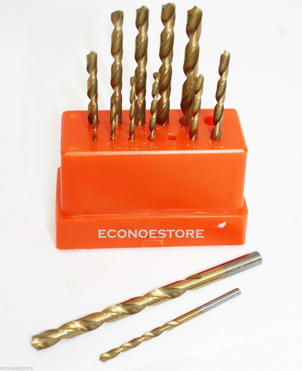
This mode is used when you want to drill into concrete, stone or masonry.
When you set the hammer drill setting to ‘on’, the drill starts to hammer or punches in and out as well as spin the bit. When using a concrete drill bit and the hammer drill setting, drilling into concrete is very easy.
It allows drilling into brittle materials without too much user applied force. If you were to try this without the hammer setting, you wouldn’t have much luck making a hole in concrete!
The hammer action function makes all the difference when it comes to drilling hard surfaces.
| Symbol | Mode | Action / Used For |
| Drilling | Drilling into wood, metal or plastic. | |
| Driving Screws | Driving screws without ripping them or bury them in the material. | |
| Hammer Action | Drilling into concrete, stone or masonry. |
What’s the Reverse Switch Symbol on a Drill?
We can’t forget about the reverse switch function, which is usually found just above or behind the trigger of the drill. You will either notice a small button or a small lever.
There isn’t a universal symbol for this function. I have a few drills and the one has an arrow in a circle going one way on one side and the other way on the other side. On another drill, it looks like a wedge facing one way on one side and the other way on the other side.
What Does ‘Nm’ Mean on a Cordless Drill?
Torque is measured in Newton Metres or ‘Nm’, which is the force that allows an object to rotate. This is the best way to gauge how powerful your drill or impact driver is. The higher the number in Newton Metres, the more twisting force your drill will have.
Torque Control on Cordless Drill vs Cordless Impact Driver
We’ve been discussing torque (and its symbols or settings) on a normal cordless drill. Regarding a cordless impact driver, it’s important to note that these tools do not have a torque control.
The only way to adjust torque on an impact driver is to use the speed control trigger. Or, if you’re just searching for a new drill, choose an impact driver with gears.
More advanced models have up to three gear ranges. You’ll spend a bit more money, but in the long run, it’s probably worth it!
What is a High Torque Drill? (Speaking of Torque)
High torque drills are low-geared rotary drills that can produce high levels of rotational force. This allows the tool to perform a variety of tasks, from mixing paint and plaster to drill pilot holes in dense wood or thick metal.
The Makita LXT Lithium-Ion cordless drill ½” hammer driver-drill is considered the most powerful tool on the market today! The brushless motor can deliver 1,090 in. lbs. Max Torque.
It can reach speeds of up to 2,100 RPM and covers a wide range of drilling, driving, and hammering applications.
So, why not go online and check it out at Amazon.com today! Your next DYI project will be hit.
⭐️ ToolsOwner’s Choice
Makita LXT High Torque Combo Kit
Buy on Amazon
(*Amazon Affiliate Link)
Conclusion
To summarize, the numbers on a cordless drill represent the torque or rotary force of the tool. The higher the number, the greater the torquing power.
This is a very useful feature on a drill. Not only does it allow you to adjust the amount of twisting power applied to screws, but it also provides the ability to bore holes in very hard substances such as wood, concrete, masonry, and metal.
Hopefully, you’ve found the information in this article helpful. Good luck with your future woodworking or DYI projects!
Cheers, tools owners!
Jack Adams
Hi there! My name is Jack and I write for ToolsOwner. I have a passion for everything related to tools and DIY projects around the house. You often find me in my workshop working on new projects.
How to Use a Drill
Drills are used in almost every DIY and home improvement project, but do you really know how to adjust one to maximize its effectiveness? To properly use a drill it takes more than just fitting the bit and pulling the trigger. We’re breaking down all of the drill/driver adjustments on this DeWalt drill, but these settings are universal across all brands.
Advertisement – Continue Reading Below
Forward/Reverse Control
Every drill has a forward and reverse control. It’s a sliding switch that indicates and changes the direction a drill is driving depending on which way it is pressed. There should be corresponding arrows on each side of the switch to help indicate direction. By setting the switch in the center position, it will lock the tool. So if your battery is charged and you can’t figure out why the drill won’t work, then make sure it’s set in either forward or reverse and not off.
Set the Speed
Most drill/drivers have two speeds, but this one has three for an even finer adjustment. The adjustable gearing provides versatility based on the task you will be performing. Setting 1 is low speed/high torque and is best for driving screws. Setting 2 is a medium speed/torque and can be used for drilling or driving. Setting 3 is the highest speed and is meant for drilling or driving fasteners. Do not adjust the speed switch unless the tool is at a complete stop, or you can damage the gearing.
Adjust the Clutch
The clutch setting is is the most important feature to have dialed in. You’ll see a list of numbers from 1 to 10 or 20. These are used to set the clutch to deliver a torque range. The higher the number on the collar, the higher the torque and the larger the fastener that can be driven. To adjust your clutch, align the arrow to a lower setting and start driving a screw. If there is too much resistance, the clutch will disengage the motor. Adjust the clutch to a higher number and find the sweet spot that will drive your screw to the desired depth without disengaging the motor or overdriving the screw.
Drill and Hammer Drill Setting
Past the highest number on the clutch setting will be an icon of a drill bit. Place the arrow on the drill icon when you want to drill. If your drill is equipped with a hammer drill setting, you’ll also see a hammer icon. This setting will engage the hammer mechanism inside the drill which will deliver concussive blows behind the drill bit to assist in drilling into brick and masonry.
Note of caution: Do not use either of these settings when driving screws or fasteners. The drill will not clutch, which means the motor will not disengage but it will stall if overloaded, causing a sudden twist. This can cause a serious wrist or hand injury.
Keyless Chuck Adjustment
To attach drill and driver bits, you’ll need to open up the chuck which will spread the teeth wide enough for you to slide the bit in. Rotate the sleeve of the chuck counter-clockwise (as viewed from the front) far enough to accept the bit. Insert the bit about 3/4 of an inch and tighten the bit in place by rotating the sleeve clockwise until you hear a click or it stops. A keyless chuck is meant to only be hand tightened. With a hex bit, make sure the teeth are firmly clamped against the sides of the bit.
Pull the trigger and look for wobble. If the bit isn’t seated correctly you’ll immediately notice how much it wanders.
A shortcut for installing a bit without so much twisting is to place the drill in reverse, grasp the end of the chuck, and slowly pull the trigger to open the bit. Then drop the bit into the chuck, switch the drill into forward position, and slowly pull the trigger while holding the chuck in place. You’ll need to release the trigger and hand tighten to make sure the bit is seated correctly.
Drill Handle
Hammer drills are equipped with a removable handle that, when attached, offers a little more control and leverage to push the drill into cement or brick. To attach the handle, twist it counter-clockwise to loosen it enough to slide over the front of the drill then twist it clockwise to right it around the collar.
Charge Indicator
Many cordless tools will have an indicator battery pack that will indicate how much of a charge your battery has left. Push on the battery icon to turn on the indicator light. Some tools will also have these lights built into the tool if it’s not on the battery. Many times when a battery dies, they simply stop working with no slow-down or notice. These indicators make sure there are no surprises.
Timothy Dahl
DIY Editor
Timothy is a lifelong DIY enthusiast who is fixated on smart home tech, beautiful tools, and wrenching on his FJ62 Land Cruiser.
This content is created and maintained by a third party, and imported onto this page to help users provide their email addresses. You may be able to find more information about this and similar content at piano.io
Advertisement – Continue Reading Below
How to Use a Drill
When to Use the Reverse Switch on Your Drill
All power drills have a forward (clockwise) and reverse (counter-clockwise) switch, usually right above the trigger. After drilling, setting the bit direction to reverse spins it counterclockwise to help it come out of the hole cleanly and easily. You’ll also use reverse mode to quickly remove screws and other fasteners.
Never Leave a Bit Behind: About Bit Holders
Drills with an on-board bit holder can save you time and hassle because the bits you need are always accessible.
Shed Light on Your Work with an LED
Some drills, 20V MAX* Lithium Ion Drill/Driver, feature a built-in LED to illuminate your work surface. This can be a lifesaver when you’re drilling or driving in tight or dark spaces like inside a closet or under the sink.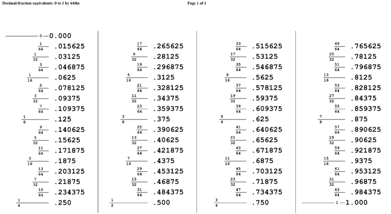
Speed Control Can Be Simple or Sophisticated
Most drill/drivers have a trigger to control how fast the drill spins, so for basic projects, a one-speed drill is all you need. If you need more precise speed control for diverse drilling or driving projects, a multi-speed drill like the BLACK+DECKER™ 20V MAX* Lithium Ion 2-Speed Drill/Driver is worth a look. Use high speed for small, fast holes and driving and a low speed for high-torque applications like drilling large holes.
Drill, Driver, or Both?
Simply, drilling is making a hole, and driving is securing a screw or other fastener. Drill/Drivers do both jobs, which is convenient for projects like hanging a mirror, where you might drill a pilot hole then drive in a screw.
Clutch Play: What Does a Drill Clutch do?
Drill/Drivers feature a manual or automatic clutch mechanism to adjust the drill/driver’s torque (turning power). Drill/Drivers with automatic clutches, like this 20V MAX* Lithium Ion Drill/Driver with AutoSense™ Technology, are great for beginners because they take the trial-and-error out of getting just the right amount of torque. Torque control is what separates a drill/driver from an ordinary drill. Most manual clutch drill/drivers have a numbered dial that makes torque adjustment easy. Use less torque (a lower number) for softer materials like drywall or when you want to limit how deep the screw goes. Use more torque for hard woods or when you want the screw flush or countersunk. When you’re not driving, simply set the clutch dial on drill mode.
Meet Chuck: What is the Drill Chuck For?
The chuck is a three-point clamp that holds the bit securely in place. Some drills come with a small key to tighten the chuck, while keyless chucks are tightened by hand. A clockwise turn tightens the chuck; a counter-clockwise turn releases the bit. Chucks come in dual-sleeve and single-sleeve configurations, with single-sleeve offering easy one-handed operation.
Corded vs. Cordless Drills
Cordless drills are convenient, compact, and easy to maneuver, so they can be used anywhere.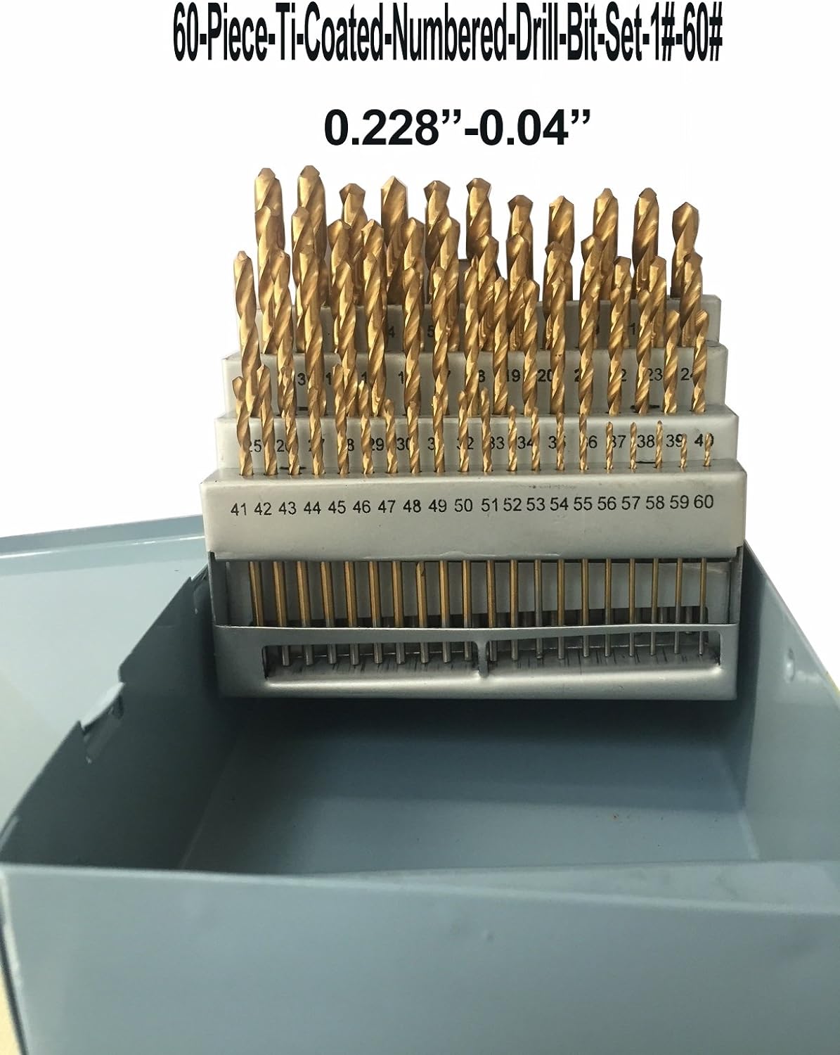 You’ll appreciate cordless flexibility when you’re out in the yard repairing a gate or up on a ladder installing a light fixture. A lithium-powered cordless drill such as our 20V MAX* Lithium Ion Drill/Driver will give you plenty of runtime for basic projects.
Corded drills require a power source and tether you to a cord, but they offer the benefit of unlimited runtime and increased power for large or complex project you want to finish without recharging a battery. You can’t go wrong with a corded drill like this BLACK+DECKER™ 20V MAX* Lithium Ion Drill/Driver.
Drill Size Chart – Machining
The drill size chart provides a list of standard size drill bits in several
measurement systems, including fractional, metric, wire gauge number, and letter. The decimal
equivalents of the diameters are shown in both English and Metric units. Fractional sizes are
measured in inches, while metric sizes are measured in millimeters. The wire gauge and letter
systems refer to tool diameters that increase as the wire gauge decreases from #107 to #1 and
then continues from A to Z. The drill size chart contains tools up to 1.5 inches in diameter,
but larger tools are also commonly used.
Downloadable versions:
English | Metric |
Drill size standard:
Fractional
Letter
Wire Gauge
Metric
| Drill size | Diameter (in) | Diameter (mm) |
|---|---|---|
| #107 | 0.0019 | 0.0483 |
| 0.05 mm | 0.0020 | 0.0500 |
| #106 | 0.0023 | 0.0584 |
| #105 | 0.0027 | 0. 0686 0686 |
| #104 | 0.0031 | 0.0787 |
| #103 | 0.0035 | 0.0889 |
| #102 | 0.0039 | 0.0991 |
| 0.1 mm | 0.0039 | 0.1000 |
| #101 | 0.0043 | 0.1092 |
| #100 | 0.0047 | 0.1194 |
| #99 | 0.0051 | 0.1295 |
| #98 | 0.0055 | 0.1397 |
| #97 | 0.0059 | 0.1499 |
| #96 | 0.0063 | 0.1600 |
| #95 | 0.0067 | 0.1702 |
| #94 | 0.0071 | 0.1803 |
| #93 | 0.0075 | 0.1905 |
| 0.2 mm | 0.0079 | 0.2000 |
| #92 | 0.0079 | 0.2007 |
| #91 | 0.0083 | 0.2108 |
| #90 | 0.0087 | 0.2210 |
| #89 | 0.0091 | 0.2311 |
| #88 | 0.0095 | 0.2413 |
| #87 | 0. 0100 0100 | 0.2540 |
| #86 | 0.0105 | 0.2667 |
| #85 | 0.0110 | 0.2794 |
| #84 | 0.0115 | 0.2921 |
| 0.3 mm | 0.0118 | 0.3000 |
| #83 | 0.0120 | 0.3048 |
| #82 | 0.0125 | 0.3175 |
| #81 | 0.0130 | 0.3302 |
| #80 | 0.0135 | 0.3429 |
| #79 | 0.0145 | 0.3680 |
| 1/64 in | 0.0156 | 0.3969 |
| 0.4 mm | 0.0158 | 0.4000 |
| #78 | 0.0160 | 0.4064 |
| #77 | 0.0180 | 0.4572 |
| 0.5 mm | 0.0197 | 0.5000 |
| #76 | 0.0200 | 0.5080 |
| #75 | 0.0210 | 0.5334 |
| #74 | 0.0225 | 0.5715 |
| 0.6 mm | 0.0236 | 0.6000 |
| #73 | 0.0240 | 0.6096 |
| #72 | 0. 0250 0250 | 0.6350 |
| #71 | 0.0260 | 0.6604 |
| 0.7 mm | 0.0276 | 0.7000 |
| #70 | 0.0280 | 0.7112 |
| #69 | 0.0292 | 0.7417 |
| #68 | 0.0310 | 0.7874 |
| 1/32 in | 0.0313 | 0.7938 |
| 0.8 mm | 0.0315 | 0.8000 |
| #67 | 0.0320 | 0.8128 |
| #66 | 0.0330 | 0.8382 |
| #65 | 0.0350 | 0.8890 |
| 0.9 mm | 0.0354 | 0.9000 |
| #64 | 0.0360 | 0.9144 |
| #63 | 0.0370 | 0.9398 |
| #62 | 0.0380 | 0.9652 |
| #61 | 0.0390 | 0.9906 |
| 1 mm | 0.0394 | 1.0000 |
| #60 | 0.0400 | 1.0160 |
| #59 | 0.0410 | 1.0414 |
| #58 | 0.0420 | 1.0668 |
| #57 | 0.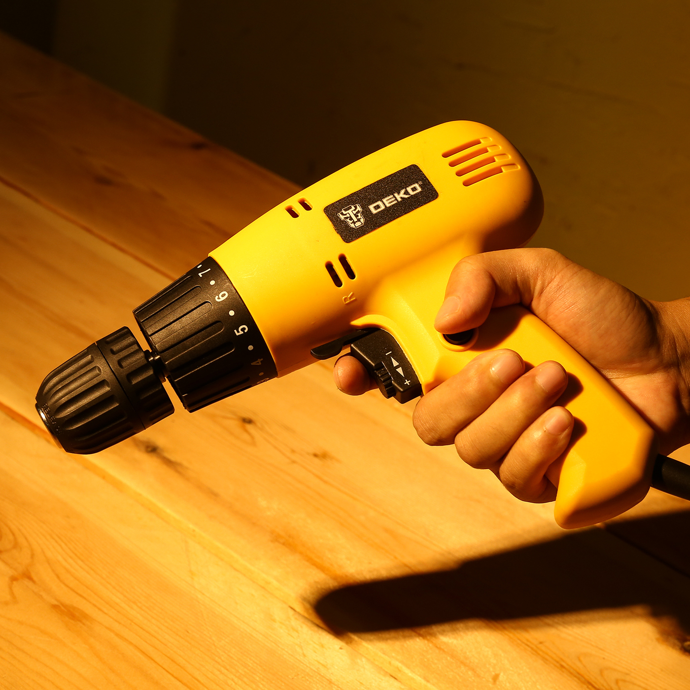 0430 0430 | 1.0922 |
| 1.1 mm | 0.0433 | 1.1000 |
| #56 | 0.0465 | 1.1811 |
| 3/64 in | 0.0469 | 1.1906 |
| 1.2 mm | 0.0472 | 1.2000 |
| 1.3 mm | 0.0512 | 1.3000 |
| #55 | 0.0520 | 1.3208 |
| #54 | 0.0550 | 1.3970 |
| 1.4 mm | 0.0551 | 1.4000 |
| 1.5 mm | 0.0591 | 1.5000 |
| #53 | 0.0595 | 1.5113 |
| 1/16 in | 0.0625 | 1.5875 |
| 1.6 mm | 0.0630 | 1.6000 |
| #52 | 0.0635 | 1.6129 |
| 1.7 mm | 0.0669 | 1.7000 |
| #51 | 0.0670 | 1.7018 |
| #50 | 0.0700 | 1.7780 |
| 1.8 mm | 0.0709 | 1.8000 |
| #49 | 0.0730 | 1.8542 |
| 1.9 mm | 0. 0748 0748 | 1.9000 |
| #48 | 0.0760 | 1.9304 |
| 5/64 in | 0.0781 | 1.9844 |
| #47 | 0.0785 | 1.9939 |
| 2 mm | 0.0787 | 2.0000 |
| #46 | 0.0810 | 2.0574 |
| #45 | 0.0820 | 2.0828 |
| 2.1 mm | 0.0827 | 2.1000 |
| #44 | 0.0860 | 2.1844 |
| 2.2 mm | 0.0866 | 2.2000 |
| #43 | 0.0890 | 2.2606 |
| 2.3 mm | 0.0906 | 2.3000 |
| #42 | 0.0935 | 2.3749 |
| 3/32 in | 0.0938 | 2.3813 |
| 2.4 mm | 0.0945 | 2.4000 |
| #41 | 0.0960 | 2.4384 |
| #40 | 0.0980 | 2.4892 |
| 2.5 mm | 0.0984 | 2.5000 |
| #39 | 0.0995 | 2.5273 |
| #38 | 0.1015 | 2. 5781 5781 |
| 2.6 mm | 0.1024 | 2.6000 |
| #37 | 0.1040 | 2.6416 |
| 2.7 mm | 0.1063 | 2.7000 |
| #36 | 0.1065 | 2.7051 |
| 7/64 in | 0.1094 | 2.7781 |
| #35 | 0.1100 | 2.7940 |
| 2.8 mm | 0.1102 | 2.8000 |
| #34 | 0.1110 | 2.8194 |
| #33 | 0.1130 | 2.8702 |
| 2.9 mm | 0.1142 | 2.9000 |
| #32 | 0.1160 | 2.9464 |
| 3 mm | 0.1181 | 3.0000 |
| #31 | 0.1200 | 3.0480 |
| 3.1 mm | 0.1221 | 3.1000 |
| 1/8 in | 0.1250 | 3.1750 |
| 3.2 mm | 0.1260 | 3.2000 |
| #30 | 0.1285 | 3.2639 |
| 3.3 mm | 0.1299 | 3.3000 |
| 3.4 mm | 0.1339 | 3. 4000 4000 |
| #29 | 0.1360 | 3.4544 |
| 3.5 mm | 0.1378 | 3.5000 |
| #28 | 0.1405 | 3.5687 |
| 9/64 in | 0.1406 | 3.5719 |
| 3.6 mm | 0.1417 | 3.6000 |
| #27 | 0.1440 | 3.6576 |
| 3.7 mm | 0.1457 | 3.7000 |
| #26 | 0.1470 | 3.7338 |
| #25 | 0.1495 | 3.7973 |
| 3.8 mm | 0.1496 | 3.8000 |
| #24 | 0.1520 | 3.8608 |
| 3.9 mm | 0.1535 | 3.9000 |
| #23 | 0.1540 | 3.9116 |
| 5/32 in | 0.1563 | 3.9688 |
| #22 | 0.1570 | 3.9878 |
| 4 mm | 0.1575 | 4.0000 |
| #21 | 0.1590 | 4.0386 |
| #20 | 0.1610 | 4.0894 |
| 4.1 mm | 0.1614 | 4.1000 |
4. 2 mm 2 mm | 0.1654 | 4.2000 |
| #19 | 0.1660 | 4.2164 |
| 4.3 mm | 0.1693 | 4.3000 |
| #18 | 0.1695 | 4.3053 |
| 11/64 in | 0.1719 | 4.3656 |
| #17 | 0.1730 | 4.3942 |
| 4.4 mm | 0.1732 | 4.4000 |
| #16 | 0.1770 | 4.4958 |
| 4.5 mm | 0.1772 | 4.5000 |
| #15 | 0.1800 | 4.5720 |
| 4.6 mm | 0.1811 | 4.6000 |
| #14 | 0.1820 | 4.6228 |
| #13 | 0.1850 | 4.6990 |
| 4.7 mm | 0.1850 | 4.7000 |
| 3/16 in | 0.1875 | 4.7625 |
| 4.8 mm | 0.1890 | 4.8000 |
| #12 | 0.1890 | 4.8006 |
| #11 | 0.1910 | 4.8514 |
| 4.9 mm | 0.1929 | 4.9000 |
| #10 | 0. 1935 1935 | 4.9149 |
| #9 | 0.1960 | 4.9784 |
| 5 mm | 0.1969 | 5.0000 |
| #8 | 0.1990 | 5.0546 |
| 5.1 mm | 0.2008 | 5.1000 |
| #7 | 0.2010 | 5.1054 |
| 13/64 in | 0.2031 | 5.1594 |
| #6 | 0.2040 | 5.1816 |
| 5.2 mm | 0.2047 | 5.2000 |
| #5 | 0.2055 | 5.2197 |
| 5.3 mm | 0.2087 | 5.3000 |
| #4 | 0.2090 | 5.3086 |
| 5.4 mm | 0.2126 | 5.4000 |
| #3 | 0.2130 | 5.4102 |
| 5.5 mm | 0.2165 | 5.5000 |
| 7/32 in | 0.2188 | 5.5563 |
| 5.6 mm | 0.2205 | 5.6000 |
| #2 | 0.2210 | 5.6134 |
| 5.7 mm | 0.2244 | 5.7000 |
| #1 | 0.2280 | 5. 7912 7912 |
| 5.8 mm | 0.2284 | 5.8000 |
| 5.9 mm | 0.2323 | 5.9000 |
| A | 0.2340 | 5.9436 |
| 15/64 in | 0.2344 | 5.9531 |
| 6 mm | 0.2362 | 6.0000 |
| B | 0.2380 | 6.0452 |
| 6.1 mm | 0.2402 | 6.1000 |
| C | 0.2420 | 6.1468 |
| 6.2 mm | 0.2441 | 6.2000 |
| D | 0.2460 | 6.2484 |
| 6.3 mm | 0.2480 | 6.3000 |
| 1/4 in | 0.2500 | 6.3500 |
| E | 0.2500 | 6.3500 |
| 6.4 mm | 0.2520 | 6.4000 |
| 6.5 mm | 0.2559 | 6.5000 |
| F | 0.2570 | 6.5278 |
| 6.6 mm | 0.2598 | 6.6000 |
| G | 0.2610 | 6.6294 |
| 6.7 mm | 0.2638 | 6.7000 |
| 17/64 in | 0.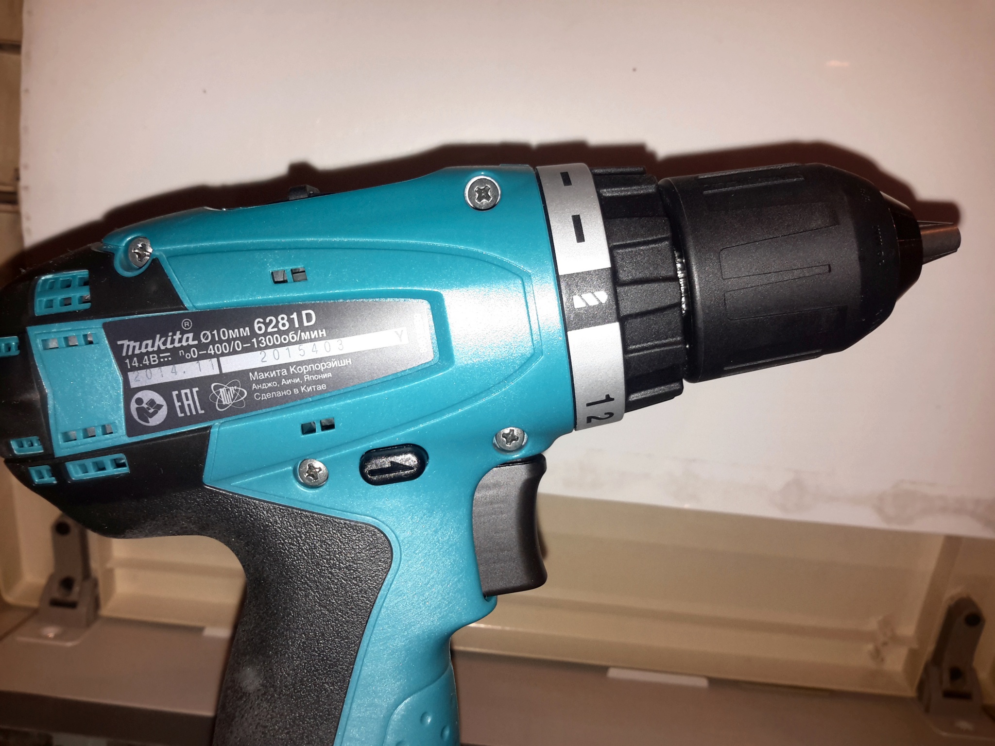 2656 2656 | 6.7469 |
| H | 0.2660 | 6.7564 |
| 6.8 mm | 0.2677 | 6.8000 |
| 6.9 mm | 0.2717 | 6.9000 |
| I | 0.2720 | 6.9088 |
| 7 mm | 0.2756 | 7.0000 |
| J | 0.2770 | 7.0358 |
| 7.1 mm | 0.2795 | 7.1000 |
| K | 0.2810 | 7.1374 |
| 9/32 in | 0.2813 | 7.1438 |
| 7.2 mm | 0.2835 | 7.2000 |
| 7.3 mm | 0.2874 | 7.3000 |
| L | 0.2900 | 7.3660 |
| 7.4 mm | 0.2913 | 7.4000 |
| M | 0.2950 | 7.4930 |
| 7.5 mm | 0.2953 | 7.5000 |
| 19/64 in | 0.2969 | 7.5406 |
| 7.6 mm | 0.2992 | 7.6000 |
| N | 0.3020 | 7.6708 |
| 7.7 mm | 0.3032 | 7. 7000 7000 |
| 7.8 mm | 0.3071 | 7.8000 |
| 7.9 mm | 0.3110 | 7.9000 |
| 5/16 in | 0.3125 | 7.9375 |
| 8 mm | 0.3150 | 8.0000 |
| O | 0.3160 | 8.0264 |
| 8.1 mm | 0.3189 | 8.1000 |
| 8.2 mm | 0.3228 | 8.2000 |
| P | 0.3230 | 8.2042 |
| 8.3 mm | 0.3268 | 8.3000 |
| 21/64 in | 0.3281 | 8.3344 |
| 8.4 mm | 0.3307 | 8.4000 |
| Q | 0.3320 | 8.4328 |
| 8.5 mm | 0.3347 | 8.5000 |
| 8.6 mm | 0.3386 | 8.6000 |
| R | 0.3390 | 8.6106 |
| 8.7 mm | 0.3425 | 8.7000 |
| 11/32 in | 0.3438 | 8.7313 |
| 8.8 mm | 0.3465 | 8.8000 |
| S | 0.3480 | 8. 8392 8392 |
| 8.9 mm | 0.3504 | 8.9000 |
| 9 mm | 0.3543 | 9.0000 |
| T | 0.3580 | 9.0932 |
| 9.1 mm | 0.3583 | 9.1000 |
| 23/64 in | 0.3594 | 9.1281 |
| 9.2 mm | 0.3622 | 9.2000 |
| 9.3 mm | 0.3661 | 9.3000 |
| U | 0.3680 | 9.3472 |
| 9.4 mm | 0.3701 | 9.4000 |
| 9.5 mm | 0.3740 | 9.5000 |
| 3/8 in | 0.3750 | 9.5250 |
| V | 0.3770 | 9.5758 |
| 9.6 mm | 0.3780 | 9.6000 |
| 9.7 mm | 0.3819 | 9.7000 |
| 9.8 mm | 0.3858 | 9.8000 |
| W | 0.3860 | 9.8044 |
| 9.9 mm | 0.3898 | 9.9000 |
| 25/64 in | 0.3906 | 9.9219 |
| 10 mm | 0.3937 | 10. 0000 0000 |
| X | 0.3970 | 10.0838 |
| Y | 0.4040 | 10.2616 |
| 13/32 in | 0.4063 | 10.3188 |
| Z | 0.4130 | 10.4902 |
| 10.5 mm | 0.4134 | 10.5000 |
| 27/64 in | 0.4219 | 10.7156 |
| 11 mm | 0.4331 | 11.0000 |
| 7/16 in | 0.4375 | 11.1125 |
| 11.5 mm | 0.4528 | 11.5000 |
| 29/64 in | 0.4531 | 11.5094 |
| 15/32 in | 0.4688 | 11.9063 |
| 12 mm | 0.4724 | 12.0000 |
| 31/64 in | 0.4844 | 12.3031 |
| 12.5 mm | 0.4921 | 12.5000 |
| 1/2 in | 0.5000 | 12.7000 |
| 13 mm | 0.5118 | 13.0000 |
| 33/64 in | 0.5156 | 13.0969 |
| 17/32 in | 0.5313 | 13.4938 |
13. 5 mm 5 mm | 0.5315 | 13.5000 |
| 35/64 in | 0.5469 | 13.8906 |
| 14 mm | 0.5512 | 14.0000 |
| 9/16 in | 0.5625 | 14.2875 |
| 14.5 mm | 0.5709 | 14.5000 |
| 37/64 in | 0.5781 | 14.6844 |
| 15 mm | 0.5906 | 15.0000 |
| 19/32 in | 0.5938 | 15.0813 |
| 39/64 in | 0.6094 | 15.4781 |
| 15.5 mm | 0.6102 | 15.5000 |
| 5/8 in | 0.6250 | 15.8750 |
| 16 mm | 0.6299 | 16.0000 |
| 41/64 in | 0.6406 | 16.2719 |
| 16.5 mm | 0.6496 | 16.5000 |
| 17 mm | 0.6693 | 17.0000 |
| 43/64 in | 0.6719 | 17.0656 |
| 11/16 in | 0.6875 | 17.4625 |
| 17.5 mm | 0.6890 | 17.5000 |
| 45/64 in | 0. 7031 7031 | 17.8594 |
| 18 mm | 0.7087 | 18.0000 |
| 23/32 in | 0.7188 | 18.2563 |
| 18.5 mm | 0.7284 | 18.5000 |
| 47/64 in | 0.7344 | 18.6531 |
| 19 mm | 0.7480 | 19.0000 |
| 3/4 in | 0.7500 | 19.0500 |
| 49/64 in | 0.7656 | 19.4469 |
| 19.5 mm | 0.7677 | 19.5000 |
| 25/32 in | 0.7813 | 19.8438 |
| 20 mm | 0.7874 | 20.0000 |
| 51/64 in | 0.7969 | 20.2406 |
| 20.5 mm | 0.8071 | 20.5000 |
| 13/16 in | 0.8125 | 20.6375 |
| 21 mm | 0.8268 | 21.0000 |
| 53/64 in | 0.8281 | 21.0344 |
| 27/32 in | 0.8438 | 21.4313 |
| 21.5 mm | 0.8465 | 21.5000 |
| 55/64 in | 0. 8594 8594 | 21.8281 |
| 22 mm | 0.8661 | 22.0000 |
| 7/8 in | 0.8750 | 22.2250 |
| 22.5 mm | 0.8858 | 22.5000 |
| 57/64 in | 0.8906 | 22.6219 |
| 23 mm | 0.9055 | 23.0000 |
| 29/32 in | 0.9063 | 23.0188 |
| 21/23 in | 0.9130 | 23.1913 |
| 59/64 in | 0.9219 | 23.4156 |
| 23.5 mm | 0.9252 | 23.5000 |
| 15/16 in | 0.9375 | 23.8125 |
| 24 mm | 0.9449 | 24.0000 |
| 61/64 in | 0.9531 | 24.2094 |
| 24.5 mm | 0.9646 | 24.5000 |
| 31/32 in | 0.9688 | 24.6063 |
| 25 mm | 0.9843 | 25.0000 |
| 63/64 in | 0.9844 | 25.0031 |
| 1 in | 1.0000 | 25.4000 |
| 25.5 mm | 1. 0039 0039 | 25.5000 |
| 1 1/64 in | 1.0156 | 25.7969 |
| 26 mm | 1.0236 | 26.0000 |
| 1 1/32 in | 1.0313 | 26.1938 |
| 26.5 mm | 1.0433 | 26.5000 |
| 1 3/64 in | 1.0469 | 26.5906 |
| 1 1/16 in | 1.0625 | 26.9875 |
| 27 mm | 1.0630 | 27.0000 |
| 1 5/64 in | 1.0781 | 27.3844 |
| 27.5 mm | 1.0827 | 27.5000 |
| 1 3/32 in | 1.0938 | 27.7813 |
| 28 mm | 1.1024 | 28.0000 |
| 1 7/64 in | 1.1094 | 28.1781 |
| 28.5 mm | 1.1221 | 28.5000 |
| 1 1/8 in | 1.1250 | 28.5750 |
| 1 9/64 in | 1.1406 | 28.9719 |
| 29 mm | 1.1417 | 29.0000 |
| 1 5/32 in | 1.1563 | 29.3688 |
29. 5 mm 5 mm | 1.1614 | 29.5000 |
| 1 11/64 in | 1.1719 | 29.7656 |
| 30 mm | 1.1811 | 30.0000 |
| 1 3/16 in | 1.1875 | 30.1625 |
| 30.5 mm | 1.2008 | 30.5000 |
| 1 13/64 in | 1.2031 | 30.5594 |
| 1 7/32 in | 1.2188 | 30.9563 |
| 31 mm | 1.2205 | 31.0000 |
| 1 15/64 in | 1.2344 | 31.3531 |
| 31.5 mm | 1.2402 | 31.5000 |
| 1 1/4 in | 1.2500 | 31.7500 |
| 32 mm | 1.2598 | 32.0000 |
| 1 17/64 in | 1.2656 | 32.1469 |
| 32.5 mm | 1.2795 | 32.5000 |
| 1 9/32 in | 1.2813 | 32.5438 |
| 1 19/64 in | 1.2969 | 32.9406 |
| 33 mm | 1.2992 | 33.0000 |
| 1 5/16 in | 1.3125 | 33.3375 |
33. 5 mm 5 mm | 1.3189 | 33.5000 |
| 1 21/64 in | 1.3281 | 33.7344 |
| 34 mm | 1.3386 | 34.0000 |
| 1 11/32 in | 1.3438 | 34.1313 |
| 34.5 mm | 1.3583 | 34.5000 |
| 1 23/64 in | 1.3594 | 34.5281 |
| 1 3/8 in | 1.3750 | 34.9250 |
| 35 mm | 1.3780 | 35.0000 |
| 1 25/64 in | 1.3906 | 35.3219 |
| 35.5 mm | 1.3976 | 35.5000 |
| 1 13/32 in | 1.4063 | 35.7188 |
| 36 mm | 1.4173 | 36.0000 |
| 1 27/64 in | 1.4219 | 36.1156 |
| 36.5 mm | 1.4370 | 36.5000 |
| 1 7/16 in | 1.4375 | 36.5125 |
| 1 29/64 in | 1.4531 | 36.9094 |
| 37 mm | 1.4567 | 37.0000 |
| 1 15/32 in | 1.4688 | 37. 3063 3063 |
| 37.5 mm | 1.4764 | 37.5000 |
| 1 31/64 in | 1.4844 | 37.7031 |
| 38 mm | 1.4961 | 38.0000 |
| 1 1/2 in | 1.5000 | 38.1000 |
Return to top
Bit Sizes [ Decimal, Number, Letter, Metric ]
It’s very convenient to have a drill chart around with bit sizes, so we thought we’d put one here for you. It covers decimal, fractions, numbered drill bits, letter drill sizes, metric drill bits, and probably a few more things I forgot to mention.
For more on twist drills in general, see our twist drill article for all the different types and tips for holemaking with them.
Metric Drill Bit Sizes
Standard metric lengths (from standards like BS 32*) define metric drill bit sizes using this system:
For 0.2 to 0.98mm, sizes use N from 2 through 9:
- N – 0.1 mm. So for N = 2, it’s 2 – 0.1, etc.
- N – 0.1 + 0.
 02 mm
02 mm - N – 0.1 + 0.05 mm
- N – 0.1 + 0.08 mm
From 1 through 2.95mm, using N from 10 through 29, we get:
- N – 0.1 mm
- N – 0.1 + 0.05 mm
For 3 through 13.9mm, with N from 30 to 139:
For 14 through 25mm, and N from 14 through 25:
- N – 1 mm
- N – 1 + 0.25 mm
- N – 1 + 0.5 mm
- N – 1 + 0.75 mm
There are also Reynard Series of preferred metric drill sizes.
Fractional-Inch Drill Bit Sizes
Fractional-inch sizes are in common use in the US and generally run from 1/64 inch up to 1 3/4 inch in 1/64″ increments. After that they run in 1/32″ increments up to 2 1/4″, then in 1/16″ increments to 3″, 1/8″ increments to 3 1/4 inches, then there’s a 3 1/2″ size.
Decimal Equivalence Chart
A good drill size chart can also be used as a handy decimal equivalence chart as well as to convert decimal sizes to metric.
Number Drill Bit Sizes & Letter Drill Bit Sizes
The ASME B94. 11M twist drill standard establishes number drill bit sizes from size 1 to 97. In practice, you will seldom see number sizes past #80.
The numbered sizes are based on but unfortunately are not identical to the Stubs Steel Wire Gauge, which originated in 19th century Great Britain.
Letter Sizes are Imperial drill bit sizes designated A (smallest) to Z (largest).
Number and Letter Sizes are in common use in the US, and to a lesser extent the UK (rapidly moving to metric), but are no longer in use for most of the rest of the world which has gone fully metric.
Why So Many Sizes?
While it may seem logical that most holes are nice round numbers in size, certain operations benefit from a lot of intermediate sizes. Specifically, reaming and tapping. Don’t just pick the first tap drill size you come across, not even the one in our Drill Chart below. Check out our article on tap drill sizes to find a much better way.
Drill Chart
Drill Chart PDF Download
|
|
|
|
Drill Size Chart
Drill Size Chart
|
|
|
|
|
|
|
|
|
|
|
|
|
|
|
|
|
|
|
|
|
|
|
| ||
|
|
|
| ||
|
|
|
| ||
|
|
|
| ||
|
|
|
|
| |
|
|
|
|
|
|
|
|
|
|
|
|
|
|
|
|
|
|
|
|
|
|
|
|
|
|
|
|
|
|
|
|
|
|
|
|
|
|
|
|
|
|
|
|
|
|
|
|
|
|
|
|
|
|
|
|
|
|
|
|
|
|
|
|
|
|
|
|
|
|
|
|
|
|
|
|
|
|
|
|
|
|
|
|
|
|
|
|
|
|
|
|
|
|
|
|
|
|
|
|
|
|
|
|
|
|
|
|
|
|
|
|
|
|
|
|
|
|
|
|
|
|
|
|
|
|
|
|
|
|
|
|
|
|
|
|
|
|
|
|
|
|
|
|
|
|
|
|
|
|
|
|
|
|
|
|
|
|
|
|
|
|
|
|
|
|
|
|
|
|
|
|
|
|
|
|
|
|
|
|
|
|
|
|
|
|
|
|
|
|
|
|
|
|
|
|
|
|
|
|
|
|
|
|
|
|
|
|
|
|
|
|
|
|
|
|
|
|
|
|
|
|
|
|
|
|
|
|
|
|
|
|
|
|
|
|
|
|
|
|
|
|
|
|
|
|
|
|
|
|
|
|
|
|
|
|
|
|
|
|
|
|
|
|
|
|
|
|
|
|
|
|
|
|
|
|
|
|
|
|
|
|
|
|
|
|
|
|
|
|
|
|
|
|
|
|
|
|
|
|
|
|
|
|
|
|
|
|
|
|
|
|
|
|
|
|
|
|
|
|
|
|
|
|
|
|
|
|
|
|
|
|
|
|
|
|
|
|
|
|
|
|
|
|
|
|
|
|
|
|
|
|
|
|
|
|
|
|
|
|
|
|
|
|
|
|
|
|
|
|
|
|
|
|
|
|
|
|
|
|
|
|
|
|
|
|
|
|
|
|
|
|
|
|
|
|
|
|
|
|
|
|
|
|
|
|
|
|
|
|
|
|
|
|
|
|
|
|
|
|
|
|
|
|
|
|
|
|
|
|
|
|
|
|
|
|
|
|
|
|
|
|
|
|
|
|
|
|
|
|
|
|
|
|
|
|
|
|
|
|
|
|
|
|
|
|
|
|
|
|
|
|
|
|
|
|
|
|
|
|
|
|
|
|
|
|
|
|
|
|
|
|
|
|
|
|
|
|
|
|
|
|
|
|
|
|
|
|
|
|
|
|
|
|
|
|
|
|
|
|
|
|
|
|
|
|
|
|
|
|
|
|
|
|
|
|
|
|
|
|
|
|
|
|
|
|
|
|
|
|
|
|
|
|
|
|
|
|
|
|
|
|
|
|
|
|
|
|
|
|
|
|
|
|
|
|
|
|
|
|
|
|
|
|
|
|
|
|
|
|
|
|
|
|
|
|
|
|
|
|
|
|
|
|
|
|
|
|
|
|
|
|
|
|
|
|
|
|
|
|
|
|
|
|
|
|
|
|
|
|
|
|
|
|
|
|
|
|
|
|
|
|
|
|
|
|
|
|
|
|
|
|
|
|
|
|
|
|
|
|
|
|
|
|
|
|
|
|
|
|
|
|
|
|
|
|
|
|
|
|
|
|
|
|
|
|
|
|
|
|
|
|
|
|
|
|
|
|
|
|
|
|
|
|
|
|
|
|
|
|
|
|
|
|
|
|
|
|
|
|
|
|
|
|
|
|
|
|
|
|
|
|
|
|
|
|
|
|
|
|
|
|
|
|
|
|
|
|
|
|
|
|
|
|
|
|
|
|
|
|
|
|
|
|
|
|
|
|
|
|
|
|
|
|
|
|
|
|
|
|
|
|
|
|
|
|
|
|
|
|
|
|
|
|
|
|
|
|
|
|
|
|
|
|
|
|
|
|
|
|
|
|
|
|
|
|
|
|
|
|
|
|
|
|
|
|
|
|
|
|
|
|
|
|
|
|
|
|
|
|
|
21/64 |
|
|
|
0.3281 |
|
|
|
|
|
|
|
|
|
|
|
|
|
|
|
|
|
|
|
11/32 |
|
|
|
0.3438 |
|
|
|
|
|
|
|
|
|
|
|
|
|
|
|
|
|
|
|
|
|
|
|
|
|
23/64 |
|
|
|
0.3594 |
|
|
|
|
|
|
|
|
|
|
|
|
|
|
|
|
|
|
|
3/8 |
|
|
|
0.3750 |
|
|
|
V |
|
0.3770 |
|
|
|
|
|
|
|
|
|
W |
|
0.3860 |
|
25/64 |
|
|
|
0.3906 |
|
|
|
|
|
|
|
|
|
X |
|
0.3970 |
|
|
|
Y |
|
0.4040 |
|
13/32 |
|
|
|
0.4063 |
|
|
|
Z |
|
0.4130 |
|
|
|
|
|
|
|
27/64 |
|
|
|
0.4219 |
|
|
|
|
|
|
|
7/16 |
|
|
|
0.4375 |
|
|
|
|
|
|
|
|
|
|
|
|
|
|
|
|
|
|
|
|
|
|
|
|
|
|
|
|
|
|
|
|
|
|
|
|
|
|
|
|
|
|
|
|
|
|
|
|
|
|
|
|
|
|
|
|
|
|
|
|
|
|
|
|
|
|
|
|
|
|
|
|
|
|
|
|
|
|
|
|
|
|
|
|
|
|
|
|
|
|
|
|
|
|
|
|
|
|
|
|
|
|
|
|
|
|
|
|
|
|
|
|
|
|
|
|
|
|
|
|
|
|
|
|
|
|
|
|
|
|
|
|
|
|
|
|
|
|
|
|
|
|
|
|
|
|
|
|
|
|
|
|
|
|
|
|
|
|
|
|
|
|
|
|
|
|
|
|
|
|
|
|
|
|
|
|
|
|
|
|
|
|
|
|
|
|
|
|
|
|
|
|
|
|
|
|
|
|
|
|
|
|
|
|
|
|
|
|
|
|
|
|
|
|
|
|
|
49/64 |
|
|
|
0.7656 |
|
|
|
|
|
|
|
25/32 |
|
|
|
0.7813 |
|
|
|
|
|
|
|
51/64 |
|
|
|
0.7969 |
|
|
|
|
|
|
|
13/16 |
|
|
|
0.8125 |
|
|
|
|
|
|
|
53/64 |
|
|
|
0.8281 |
|
27/32 |
|
|
|
0.8438 |
|
|
|
|
|
|
|
55/64 |
|
|
|
0.8594 |
|
|
|
|
|
|
|
7/8 |
|
|
|
0.8750 |
|
|
|
|
|
|
|
|
|
|
|
|
|
|
|
|
|
|
|
|
|
|
|
|
|
|
|
|
|
|
|
|
|
|
|
|
|
|
|
|
|
|
|
|
|
|
|
|
|
|
|
|
|
|
|
|
|
|
|
|
|
|
|
|
|
|
|
|
|
|
|
|
|
63/64 |
|
|
|
0.9844 |
|
|
|
|
|
|
Drilling holes on drilling machines
For drilling, the part is securely fixed directly on the machine table or on special tables. When drilling holes, various coolants are used, selecting them so that they can simultaneously protect the material from corrosion. A 2% caustic soda solution is usually used to cool the drills when machining steel.
Very often, when drilling carbon steels of ordinary quality, a drilling emulsion (a mixture of water with drilling oil or lard) is used, and when drilling alloy steels, a surrogate from rapeseed oil (a mixture of rapeseed oil with kerosene) is used.
Before starting drilling, the machine is inspected, it is checked whether it is in good working order, the rubbing parts are lubricated with oil and the number of revolutions per minute and the drill feed are set. The number of revolutions per minute of the drill is determined depending on the properties of the material being processed and the diameter of the drill. The number of revolutions of drills is determined by counting, using formulas, or from tables. Knowing the characteristics of the processed steel and the diameter of the drill, according to the table. 7 select the cutting speed and feed.Then, according to the conversion table. 8 translates the cutting speed to the drill rpm.
Table 7. Feed rates and cutting speeds when drilling holes with twist drills
| Drill | Name of the processed material | ||||||
| Material | Diameter, mm | Carbon steel, cast iron | Copper, aluminum | Brass | |||
| S 0 mm / rev | σ m / min | S 0 mm / rev | σ m / min | S 0 mm / rev | σ m / min | ||
| Carbon Tool Steel | 5 to 10 | 0.15-0.2 | 8-12 | 0.2-0.3 | 20-25 | 0.15-0.2 | 10-13 |
| 10 to 20 | 0.15-0.25 | 10-13 | 0.25-0.35 | 20-30 | 0.15-0.25 | 13-15 | |
| Over 20 | 0.05-0.15 | 10-13 | 0.15-0.25 | 20-30 | 0.05-0.15 | 13-16 | |
| High speed steel | 5 to 10 | 0.15-0.2 | 20-30 | 0.2-0.3 | 40-60 | 0.15-0.2 | 25-30 |
| 10 to 20 | 0.15-0.25 | 25-35 | 0.25-0.35 | 50-70 | 0.15-0.25 | 30-40 | |
| Over 20 | 0.05-0.15 | 30-35 | 0.15-0.25 | 60-70 | 0.05-0.15 | 35-40 | |
Table 8.The number of revolutions per minute of the drill depending on its diameter and cutting speed
| Diameter drills, mm | Cutting speed, m / min | |||||||||
| 10 | 15 | 20 | 25 | 30 | 35 | 40 | 45 | 50 | 60 | |
| Revolutions n per minute | ||||||||||
| 1 | 3180 | 4780 | 6370 | 7960 | 9550 | 11 150 | 12 730 | 14 330 | 15 920 | 19 100 |
| 2 | 1590 | 2390 | 3190 | 3980 | 4780 | 5 580 | 6 370 | 8 060 | 7 960 | 9 560 |
| 3 | 1061 | 1590 | 2120 | 2660 | 3180 | 3 720 | 4 250 | 4 780 | 5 320 | 6 360 |
| 4 | 796 | 1195 | 1595 | 1990 | 2390 | 2 790 | 3185 | 3 595 | 3 980 | 4 780 |
| 5 | 637 | 955 | 1275 | 1590 | 1910 | 2 230 | 2 550 | 2865 | 3 180 | 3 820 |
| 6 | 530 | 796 | 1061 | 1326 | 1590 | 1 855 | 2 120 | 2 387 | 2 622 | 3 180 |
| 7 | 455 | 682 | 910 | 1135 | 1365 | 1 590 | 1 820 | 2 045 | 2 270 | 2 730 |
| 8 | 398 | 597 | 796 | 996 | 1191 | 1 392 | 1 590 | 1 792 | 1 992 | 2 338 |
| 9 | 353 | 530 | 708 | 885 | 1061 | 1 238 | 1 415 | 1 593 | 1 770 | 2122 |
| 10 | 318 | 478 | 637 | 796 | 955 | 1 114 | 1 273 | 1 433 | 1 592 | 1 910 |
| 12 | 265 | 398 | 530 | 663 | 796 | 929 | 1 061 | 1 193 | 1 326 | 1 592 |
| 14 | 227 | 341 | 455 | 568 | 682 | 796 | 910 | 1 010 | 1 136 | 1 364 |
| 16 | 199 | 298 | 378 | 497 | 597 | 696 | 795 | 895 | 994 | 1 194 |
| 18 | 177 | 265 | 353 | 442 | 531 | 619 | 708 | 795 | 884 | 1 062 |
| 20 | 159 | 239 | 318 | 398 | 478 | 558 | 637 | 716 | 796 | 956 |
| 22 | 145 | 217 | 290 | 362 | 435 | 507 | 580 | 652 | 724 | 870 |
| 24 | 132 | 199 | 265 | 332 | 398 | 465 | 531 | 597 | 664 | 796 |
| 26 | 122 | 184 | 245 | 306 | 368 | 429 | 490 | 551 | 612 | 736 |
| 27 | 113 | 171 | 227 | 284 | 341 | 398 | 455 | 511 | 568 | 682 |
| 30 | 106 | 159 | 213 | 265 | 318 | 371 | 425 | 478 | 530 | 636 |
| 32 | 99 | 149 | 199 | 249 | 298 | 348 | 398 | 448 | 498 | 596 |
| 34 | 93 | 140 | 187 | 234 | 280 | 327 | 374 | 421 | 468 | 560 |
| 36 | 88 | 133 | 177 | 221 | 265 | 310 | 354 | 398 | 442 | 530 |
| 38 | 84 | 126 | 168 | 210 | 251 | 294 | 336 | 378 | 420 | 504 |
| 40 | 80 | 119 | 159 | 199 | 239 | 279 | 318 | 358 | 398 | 478 |
| 42 | 76 | 113 | 152 | 189 | 227 | 265 | 307 | 341 | 378 | 452 |
| 46 | 71 | 106 | 142 | 177 | 217 | 248 | 283 | 319 | 354 | 426 |
| 50 | 64 | 95 | 127 | 159 | 191 | 223 | 255 | 286 | 318 | 382 |
Determined from the table.8, the number of revolutions per minute of the drill is compared with the number of revolutions per minute of the machine indicated on the plate that is attached to the machine or in the passport data of the machine, and the nearest number of revolutions that the machine can give is taken. In machines with a gearbox, the number of revolutions per minute of the spindle is set by moving the handles to the position corresponding to the selected number of revolutions. In machines with stepped pulleys, a drive belt is put on the corresponding step.
Automatic feed is set in the same way.Manual feed is not installed. The pressure on the drill during manual feed is adjusted by hand.
The following rules must be observed when drilling holes:
when receiving drills from the tool-distribution pantry, check the sharpening and condition of the cutting edges. The drill must be sharp and properly sharpened;
securely fix the drill in the spindle of the machine, since any beating of the drill leads to inaccuracy of the hole and breakage of the drill;
securely fix the workpieces on the work table;
before bringing the drill to the workpiece, start up the machine.The drill should be brought to the workpiece without sharp jolts and impacts, since in this case the cutting edges of the drill crumble;
the drill, when exiting the drilled hole, captures too much chips; therefore, at this moment it is necessary to reduce the feed, otherwise you can easily break the drill;
When drilling a deep hole, from time to time, without stopping the machine, pull the drill out of the hole to remove chips. It is necessary to remove the drill from the hole with the same direction of rotation of the drill as during work.Stopping the machine at the moment when the drill is in the hole entails jamming of the drill and its breakage;
sharpen drills in a timely manner. The drill wears out less with frequent sharpening than with severe bluntness;
“Squealing” of the drill during operation indicates that the drill is blunt or skewed in the hole. In this case, the work is stopped and it is checked whether the cutting edges are sharp and whether the drill is directed correctly;
Knock out the drill from the machine spindle with a wedge with several short blows, but not with one strong blow.
Reasons for rejects during drilling are different. The main ones are negligence in work, oversight and negligence of the worker himself, as well as insufficient knowledge of the tool and machine, malfunction of the machine and fixtures, improper installation and fastening of tools and parts, work with an incorrectly sharpened tool.
A hole larger than the specified diameter is obtained for the following reasons:
the drill is taken with a larger diameter;
Incorrect cutting edges or cutting edges of different lengths
drill play in the tapered adapter sleeve;
backlash of the machine spindle.
The hole is displaced for the following reasons: the part is marked incorrectly;
the part is incorrectly installed and loosely fixed on the machine table;
the drill has a runout in the spindle; the drill leads to the side.
Misalignment of the hole occurs for the following reasons:
the part is incorrectly installed on the machine table; chips fell under the lower surface of the part; linings are incorrectly placed under the parts; the machine table is not perpendicular to the spindle; incorrect, too strong pressure on the drill when feeding.
Holes with a roughly machined surface are obtained for the following reasons: a blunt or incorrectly sharpened drill was used; too much feed; the drill is not sufficiently cooled; drill bit and part poorly installed.
Drilling dependence of the number of revolutions on the diameter of the drill
When drilling holes in metal, the number of revolutions of the drill and the feed force applied to the drill, directed along the axis of the drill, are important factors to ensure that the drill penetrates in one revolution (mm / rev).When working with different metals and drills, different cutting conditions are recommended, and the harder the metal being processed and the larger the drill diameter, the lower the recommended cutting speed. The indicator of the correct mode is beautiful, long chips.
Table 1. Recommended hole cutting speeds L / D ≤ 3, given for medium-hard high speed steel
Feed S0, mm / rev | Drill diameter D, mm | |||||||||
2.5 | 4 | 6 | 8 | 10 | 12 | 146 | 20 | 25 | 32 | |
Cutting speed v, m / min | ||||||||||
When drilling steel | ||||||||||
0.06 | 17 | 22 | 26 | 30 | 33 | 42 | – | – | – | – |
0.10 | – | 17 | 20 | 23 | 26 | 28 | 32 | 38 | 40 | 44 |
0.15 | – | – | 18 | 20 | 22 | 24 | 27 | 30 | 33 | 35 |
0.20 | – | – | 15 | 17 | 18 | 20 | 23 | 25 | 27 | 30 |
0.30 | – | – | – | 14 | 16 | 17 | 19 | 21 | 23 | 25 |
0.40 | – | – | – | – | – | 14 | 16 | 18 | 19 | 21 |
0.60 | – | – | – | – | – | – | – | 14 | 15 | 11 |
When drilling cast iron | ||||||||||
0.06 | 18 | 22 | 25 | 27 | 29 | 30 | 32 | 33 | 34 | 35 |
0.10 | – | 18 | 20 | 22 | 23 | 24 | 26 | 27 | 28 | 30 |
0.15 | – | 15 | 17 | 18 | 19 | 20 | 22 | 23 | 25 | 26 |
0.20 | – | – | 15 | 16 | 17 | 18 | 19 | 20 | 21 | 22 |
0.30 | – | – | 13 | 14 | 15 | 16 | 17 | 18 | 19 | 19 |
0.40 | – | – | – | – | 14 | 14 | 15 | 16 | 16 | 17 |
0.60 | – | – | – | – | – | – | 13 | 14 | 15 | 15 |
0.80 | – | – | – | – | – | – | – | – | – | 13 |
When drilling aluminum alloys | ||||||||||
0.06 | 75 | – | – | – | – | – | – | – | – | – |
0.10 | 53 | 70 | 81 | 92 | 100 | – | – | – | – | – |
0.15 | 39 | 53 | 62 | 69 | 75 | 81 | 90 | – | – | – |
0.20 | – | 43 | 50 | 56 | 62 | 67 | 74 | 82 | – | – |
0.30 | – | – | 42 | 48 | 52 | 56 | 62 | 68 | 75 | – |
0.40 | – | – | – | 40 | 45 | 48 | 53 | 59 | 64 | 69 |
0.60 | – | – | – | – | 37 | 39 | 44 | 48 | 52 | 56 |
0.80 | – | – | – | – | – | – | 38 | 42 | 46 | 54 |
1.00 | – | – | – | – | – | – | – | – | – | 42 |
Table 2.Correction factors
Name and grade of the processed material | Hardness HB | Correction factor | ||
High speed drills | Solid carbide drills | |||
High-quality structural carbon steel | ||||
10, 15, 20 | 156 | 1.2 | 1.2 | |
30, 35, 40 | 143-207 | 1.3 | 1.2 | |
170-229 | 1.2 | 1.3 | ||
207-269 | 0.8 | 1.0 | ||
Table 4.Tips for drilling austenitic steel (most difficult to machine)
Drill diameter, mm | Number of revolutions, rpm | Feed, mm / rev. |
1.59 | 1500 | 0.025 |
3.18 | 800 | 0.065 |
6.35 | 400 | 0.125 |
12.70 | 150 | 0.280 |
20.64 | 180 | 0.255 |
25.40 | 150 | 0.280 |
You have no rights to post comments
Plastic drilling and threading in thin-walled metal structures
Plastic drilling and threading in thin-walled metal structures
From history
Back in 1923, Jean-Claude de Vallière made an unusual tool in a small shed in France, with which it became possible to make holes in thin steel sheets using frictional heat, rather than drilling as before.Numerous experiments were mostly successful, but it was impossible to establish its industrial use for a number of reasons due to the lack of:
– hard metal required for the tool,
– knowledge of the correct geometry of the tool,
– diamond grinding wheels for processing hard materials,
– machines for grinding complex profiles.
Therefore, it took another 60 years before all these problems were solved, and the use of extrusion drills became possible and profitable.Thus, new non-cutting extrusion drills appeared in the industry.
Extrusion drills are polygon ground carbide tools. With a sufficiently high number of revolutions and axial force of the drills on thin-walled metal products, the metal is plasticized under the action of frictional heat, and the drill freely passes through the workpiece. Simultaneously with the formation of the hole, a sleeve is formed from the heated material displaced downward. The sleeve length is several times longer than the previous material thickness.The thickness of the metal can be from 1 mm to 10 mm, depending on the diameter of the hole.
A variety of tools are available for making hardened threads in thin-walled batches, for making large bearing areas.
This drilling method has been successfully used for several decades in various industrial industries. For optimum results, the user should be familiar with the technology, extrusion drilling options and machine requirements.
Extrusion drilling process
In this description of the extrusion drilling process, we assume the use of a standard extrusion bit.
The part of the drill subject to friction is tapered (fig. 1) . The cone of the working part passes into the cylinder. The conical and cylindrical parts together form a working core. Above them there is an edge to form a tight edge of the hole and a cylindrical shank for attaching the drill to the collet.Both the conical and cylindrical parts have a polygon shape in cross-section, which is of decisive importance in the process of extrusion drilling. As a starting material for the production of extrusion drills, a specially developed for this process, resistant to abrasion and changes in thermal conditions, a hard metal alloy is used.
• Start phase
To start the process, a sufficiently high axial force and high speed are required to generate the necessary frictional heat between the extrusion drill and the workpiece.In this case, the temperature of the drill rises to 650–750 ° C, and the temperature of the workpiece – up to about 600 ° C.
The number of revolutions should be kept as low as possible to minimize downtime due to heating of the drill. The choice of the number of revolutions primarily depends on the diameter of the hole for the thread, it is also determined by the thickness and type of material. High alloyed and stainless steels require lower RPM and therefore less tool downtime. The speed should be higher for soft colored materials.In general, it should be noted: the softer the material, the more you need to select the number of revolutions.
The feed force is increased until the tip of the drill passes through the material.
• Drilling process
The displaced material first flows against the feed direction and then, when the point of the extrusion drill passes through the material, flows down in the feed direction of the drill. The feed force decreases slowly while the feed rate increases.
• Forming phase
The core of the drill pushes the material out.The feed force is reduced to zero. The edge of the extrusion drill forms an O-ring-shaped edge from the material displaced against the feed direction.
The final width and geometrical shape of the sleeve produced in this way depends on the selected hole diameter for the thread and the ratio of the tapered to cylindrical parts of the drill.
At fig. 2 shows the process of drilling an extrusion.
Drill types FLOWDRILL
• FLOWDRILL type “long”
The polygonal long cylindrical part also adjoins the polygonal friction cone of the extrusion drill (Fig.3a) .
Extruded bushings are cylindrical in shape.
At the end of the work process, the material which is displaced in the opposite direction to the feed direction by means of a flat edge is formed into a kind of sealing lip.
• FLOWDRILL Short Type
This type was specially designed for FLOWTAP thread forms in thin materials and has a clearly smaller polygonal cylindrical section (fig. 3c) than the long type. The bushings made in this way are predominantly tapered in shape, the bore decreases in diameter and the wall thickness of the bushing decreases.This shape affects the uniformity of deformation for FLOWTAP threads and as a result the tool produces fully formed threads with high strength. If the material is thicker, it is necessary to use the “long” type for the thread.
• FLOWDRILL type “flat”
This type can be combined with both types described above – “short” and “long” (fig. 3b and 3d) . Along the edge of the drill is a ground cutting edge that removes material displaced against the feed direction. As a result of drilling, a flat workpiece is obtained.The manufacturer can grind this edge for fitting only once during the entire service life.
• FLOWDRILL special shapes
In some cases, the workpiece to be machined is too flat or the pipe cross-section is not sufficient for standard length extrusion drills. Then use extra short extrusion drills with a large corner at the top.
• FLOWDRILL type “REM”
In this type, both edges of the cutting edge are ground in the conical part of the drill, which start at the tip of the drill (fig.4) . These designs can be used in hand-held drills, because the grinding of the cutting edge reduces the feed force by about 1/3. This type is used on treated or electroplated surfaces. By eliminating the surface layer, the lubricating effect of fusible substances can be avoided.
The “REM” design can be combined with all the above mentioned types. However, the use of this type of drill on low alloy steels and non-ferrous metals, as well as on materials with a maximum wall thickness of 2 mm, should be limited.
Application examples FLOWDRILL
Here are some examples:
– soldered joints of a large surface with a precise cylindrical part (base of the heat exchanger),
– sliding bearings with a high load-bearing capacity (tilting mechanism of tanning beds),
– nests of ball bearings and needle roller bearings in thin-walled tubes (coupling with a cross in the steering safety racks),
– threading.
The most common application is thread making.Therefore, we will talk about this in more detail later.
Thread forming FLOWTAP
Extrusion drilling is most commonly used to make thread holes in thin-walled pipes and sheets. Threads can of course also be tapped with taps, but in combination with extrusion drilling, we recommend cold forming with the FLOWTAP thread former (fig. 5) .
The diameter of the emboss hole thread determines the depth of the sides of the thread profile and thus the strength of the thread.
Advantages of the thread former in relation to threading:
– no waste,
– the material is retained completely to relieve the load,
– the strength of the thread increases significantly due to the compression of the material during cold working with a simultaneous continuous arrangement of fibers on the sides of the thread profile,
– significantly the working speed increases and, as a result, productivity,
– no cuts, thanks to an accurate thread guide,
– extremely long life of the cutting tool and trouble-free automation,
– applicable to all conventional threading devices.
Grease
Special lubricants have been developed for the extrusion drilling process, which must be applied in a thin layer at regular intervals between drilling. We especially recommend that you regularly lubricate the transition from the friction taper to the drill barrel and edges.
Thanks to FLOWDRILL lubricant:
– the working temperature of the drill decreases and, therefore, the tool life increases,
– the material does not remain on the drill,
– wear is reduced,
– the surface quality of the formed sleeve is higher,
– a clean edge.
Due to the high values of the deformation force during cold rolling, the frictional force increases. Therefore, a high quality FLOWTAP lubricant must be used for every forming process. At the same time, the torque becomes significantly lower, which has a beneficial effect on the service life of the thread former. The surface quality of the formed threads is greatly improved.
Extrusion drilling on CNC machines
At the beginning of the process, the thrust is very high to generate the required amount of frictional heat between the tool and the workpiece.The feed rate is almost 0. When the material starts to become pliable, the feed rate can be increased until the tip of the extrusion drill has passed the material. The required feed rate can be manually adjusted.
To simulate the above process on a CNC machine, you need to start it at a very low feed rate, which will gradually increase until the end of the process. The parameters for thread hole diameter, speed, material grade and thickness vary.
Processed materials
In general, all cut materials can be extruded.All thin-walled weldable, alloyed and unalloyed steels, aluminum alloys, copper, bronze, magnetic materials and special alloys can be processed using the described technology. All materials that can be extruded can be machined with the FLOWTAP thread former. The workability depends on the elasticity of the material.
Well suited for this:
– alloyed and unalloyed steels (also stainless and acid-resistant) with tensile strength up to approx. 700 N / mm,
– non-ferrous metals (excluding brittle metals such as CuZn40Pb2),
– light metals with silicon content less than 5%.
———————————————— ————
Information provided by the representative office of VKT Trading GmbH
Drill sharpening geometry – XXL Mechanical Engineering Encyclopedia
As a rule, in the manufacture of polymer seals, it is necessary to use a drilling operation, which presents known difficulties when working with plastics. For drilling, vertical drilling machines are used, similar to those used in metalworking.The correct choice of drill design, processing mode and lubricant is of great importance. Experience with plastics has shown that high speed, low feeds per revolution and frequent tool lifting are essential for good drilling. When drilling thermoplastics – (polyethylene, caprolon, fluoroplastic, etc.) with standard drills, the phenomenon of tightening the drill into the material and its jamming is observed. Changing the geometry of the sharpening of the drill makes it possible to eliminate this disadvantage as well.The angle of inclination of the groove should be equal to 15 – 17 °, the angle at the top – up to 70 °, the rear angle – 4 – 8 °.
[c.67]
And drills when feeding the latter. Drill sharpening geometry and cutting conditions are given in table. 44, drill designs – Table. 33.
[c.53]
When choosing the geometry of sharpening drills, depending on the diameter of the drill and the material to be processed, it is recommended to be guided by the data in Table.25.
[c.115]
In addition to the above forms of sharpening the drill, other ways to improve the geometry of twist drills can be used. So, for example, the innovative worker V.I.Zhirov developed a new geometry for sharpening drills, dry, the post of which consists in combining a double sharpening of a drill with a sharpening and cutting of its jumper. According to some reports, the sharpening and cutting of the web significantly reduces the feed force and improves the drill performance.
[c.77]
Drill-driver-innovator V.I. Zhirov developed a progressive geometry of sharpening drills, which consists in cutting a bridge, double sharpening with a sharpening of the front surface (Fig. 17).
[c.88]
There are also other proposals of innovators in production to improve the geometry of sharpening drills to improve the conditions for crushing chips and reduce the axial force.
[p.325]
GEOMETRY OF DRILL SHARPENING
[c.139]
Cutting mode when drilling and reaming is selected depending on the material of the workpiece, the diameter and geometry of the drill sharpening, the length of the hole to be machined and the drill overhang.Drilling feed rates are determined using cards 131 and 133 [10]. In this case, the upper values of the feeds (I group of feeds) are taken when drilling blind holes without tolerance or according to the 5th class of accuracy, subsequent reaming, processing with two or three tools, processing with one tool and threading with taps. The average values of feeds (group II) are used when drilling blind and through holes in parts of insufficient rigidity, subsequent threading with taps, processing with a countersink or two reamers.The minimum feed rates (group III) are used for precise holes and subsequent processing with one countersink or one reamer. The cutting speed and the number of revolutions of the drills are determined from cards 132 and 135 [10].
[c.204]
The durability of drills is greatly influenced by the geometry of their cutting part. In fig. 9.12 shows diagrams of various ways of sharpening drills aimed at improving their geometry.
[c.140]
In works completed before 1931, it was shown that drills with a constant normal rake angle should have a curved cutting edge. The curvature of the edge can be predicted theoretically. However, sharpening of a drill with this geometry presents serious difficulties and therefore is not performed. Several attempts have been made
[c.155]
Fig, 94. Durability of twist drills with different sharpening geometries.
[c.114]
S. S. Rudnik, Analytical study of the geometry of the sharpening of a twist drill.Izvestia KPI, vol. IX, Mashgiz, 1949.
[p.372]
Zhirov V.I., New geometry of sharpening high-speed drills, TsBTI,
[c.482]
Drilling of plastics is performed on high-speed metal-working machines. For drilling plastics, standard twist and tip drills are recommended, used for metal processing, with a special sharpening geometry (Table 3.26).
[c.171]
Defective drilling and its warning. The main signs of rejects during drilling are drill drift away from a given direction and a breakdown of the diameter of the machined hole.Leakage occurs when the drill is sharpened incorrectly, with an excessively large overhang of the spindle and with uneven hardness of the part or the presence of cavities in the metal. The breakdown of the hole diameter is a consequence of improper sharpening and wrong choice of drill geometry, large spindle runout and non-uniformity of the material being machined. Some of the above reasons for marriage can be eliminated by the worker himself. So, for example, before drilling long holes, you should give direction with a short IL drill and by boring the hole with a cutter to a short length.Drill sharpening should be done according to the template, achieving equal
[c.166]
Auger drills have a special geometry of sharpening (Fig. 92) flat sharpening of the front and rear surfaces with a chip breaking groove on the front surface.
[c.199]
In Fig. 57 shows a typical design of a twist drill with an indication of its main elements and sharpening geometry.
[c.138]
I a – the main elements of the drill, b – sharpening geometry
[c.138]
Sharpening of drills on flat flank surfaces requires special adjustment of the universal sharpening head, depending on the geometric parameters of the tool. The formulas for calculating the angles of installation of the head are given in table. 130.
[c.235]
Standard twist drills from P9 were used as cutting tools for the experiments. The geometry of the sharpening of the cutting part of the drills was taken in accordance with GOST 2092—60.
[c.413]
In Fig.34, a shows the sharpening of HSS drills for drilling laminated plastic. The geometry of the cutting part of such drills is given in table. 52,
[c.132]
The stated drill geometry reduces the axial force by one and a half times and accordingly increases the feed. Good chip breaking makes it possible to reduce the number of drill pins in deep drilling. Drill life increases 2-3 times. However, it should be noted that the sharpening of the drill according to the method of the Chinese innovator is quite difficult. [p.91]
VNII, Sharpening of drills from high-speed steel with geometry of V.I. Zhirova, TsBTI, Mosgorsovnarkhoz, 1957.
[c.320]
Drills with an increased cross-section (increased length of the transverse edge – web) require the application of a greater axial force. When working with such drills, the torque increases, since the geometry of the cutting elements formed by the bridge and the flanks of the drill is unfavorable. Large negative rake angles cause a kind of scraping with a blunt edge – the jumper of the drill.The influence of its length is especially significant when working with small and medium diameter drills. At the same time, if the length of the transverse edge is insufficient, the drill tip is chipped. Work on steel with drills without a bridge (sharpening of drills according to the method proposed by V.I.Zhirov) ends with its breakage – splitting along the axis in the direction of the helical groove.
[c.223]
Sharpening of improved drills does not require special tools to restore the geometry of the tool, since the chip breaking shoulders retain their size and shape after normal regrinding.The absence of long chips, which often wrap around the tool, increases the safety of work.
[c.230]
The innovator of production, driller V. I. Zhirov, developed the geometry of sharpening twist drills, the essence of which is the use of double sharpening with sharpening the front surface and cutting the jumper blade (Fig. 40, a). Average data (Table 9) on double sharpening of cutting blades are taken in accordance with GOST 2322-43, and the values of the front surface undercut and cutting of the jumper blade are compiled on the basis of the practice of V.I. Zhirov and tests carried out at the All-Union Scientific Research Instrumental Institute.
[c.86]
Tubular-blade (group 1a) and spatula drills (group 2a) are currently most widely used. Screw drills (group 16) are also used, which allow you to drill deep holes with a ratio of I yo up to 10-15 on universal machines. These drills do not belong to deep drilling tools, since when they work, the chips are not removed by the flow of coolant, but by means of helical grooves.They are given in table. 9.1 to show all the tools currently used for deep hole drilling. Ejector drills (group 3a), due to the organization of their centralized production, can be widely used. Drills with M-shaped sharpening (group 26), having a cutting part made of high-speed steel, are currently practically not used due to their low productivity. The advantages and disadvantages of each type of tool shown in the table are determined by a combination of advantages and disadvantages associated with their individual distinctive features by the way of coolant removal, the location of the cutting blades and the distribution of the load between them, the type of guide elements, the presence of a certain location, balance, etc.(see chapters 1 and 2). Below is considered the design, geometry of sharpening and features of the drilling technology currently used by the tools (from those indicated in Table 9.1).
[c.177]
Use also tubular-blade drills. In fig. 9.33 shows the design of such a drill with a diameter of 5.08 mm for vibration drilling of a hole in the nozzle body [37]. The stem part of the drill is made of a solid rod made of 40X steel, heat-treated to a hardness of 25-30 NKSe with a milled U-shaped groove with an angle of 120 °.A shank with a diameter of 10 mm is fixed at the rear end of the drill. The drill is equipped with two guide keys and a VK8 carbide cutting insert. A brass tube is soldered into a special longitudinal groove located on the opposite side of the Y-shaped groove for supplying coolant to the cutting zone. With a change in the grade of the processed material, the sharpening geometry
[c.218]
SCHEME OF DRILL SHARPENING ON DRILL- OP CONTROL OF DRILL GEOMETRY COMP-
[c.46]
Forms of sharpening drills.Drill geometry can be improved by double sharpening, undercutting and ribbing.
[c.153]
Geometrical parameters of the drill. With an increase in the angle (O, the axial force P and the moment M decrease due to an increase in the rake angles on the main cutting edges and the facilitation of chip evacuation. , and tangential P, increases, thereby increasing M.With a decrease in the angle 2ph, the cutting resistance due to an increase in y decreases, but at the same time the width of the cut increases and its thickness decreases. The latter leads to an increase in deformation (thin chips are deformed more completely) and, consequently, to an increase in force P and moment M. The cutting angle of the transverse edge is 6 5> 90 ° (see Fig. 92, b) and this significantly increases the axial force P. It was previously noted that the force acting on the lateral edge P J is the rake angle, thereby creating more favorable cutting conditions near it.The geometry of the transverse edge has little effect on the M value. Double sharpening of the drill also has little effect on P (, and M.
[c.157]
There are also other proposals of the innovators of production to improve the geometry of sharpening of drills. So, for example, to improve the conditions for chip crushing and reduce the axial force on the main cutting edges of the drills proposed by E. Ya.Esiiovich, two
[c.233]
When sharpening twist drills and cut-out countersinks, you must accurately perform their geometry.Improper sharpening can cause the cutting blades to be unequal in length and with different sharpening angles. The use of such a tool inevitably leads to an increase in the diameter of the hole, and in a number of cases without – to scrap. In order to avoid incorrect sharpening of drills, it is necessary to use special templates that control the sharpening angle of the cutting blades.
[c.199]
Sharpening of drills is carried out in sharpening workshops by specialists-sharpeners on special machines, such as, for example, machines of models 3652, 3658, 3659A, etc., providing the required geometry of the cutting part of the drill.
[c.200]
Solving the problem of the elastic aftereffect of CFRP in the hole and excluding re-drilling, which increases the cost and terms of putting the structure into operation, Northrop oi p. created a spade drill integrated with a countersink, the sharpening geometry of which is shown in Fig. 5.5 [12]. Experiments with this drill on carbon fiber reinforced plastic with a thickness of 12.7 mm showed that the optimal rotational speed is 2800 rpm and the feed rate is 0.04 mm / rev when cooling the jet.
[c.130]
A 2URI type device for measuring angles of a multi-edge cutting tool, a Pendulum goniometer of the ZURI-M type, a PKR type device for controlling the angles of prismatic cutters, a K60-6 type device for controlling the rake angle of taps. A device of the K10-17 type to control the corner at the top and the symmetry of the sharpening of drills. KZZ-5 device for controlling the geometry of end mills with a tapered shank. KZZ-4 device for testing end mills with cylindrical shank
[c.783]
Hand sharpening of drills cannot both meet these conditions. For correct drill geometry and high quality. of the sharpened surfaces, it is necessary to sharpen the drills on special machines or devices.
[c.240]
Sharpening of drills. To give the drill the necessary geometry or to recover after wear, it is sharpened. Sharpening is carried out from specialized drill-grinding flocks or manually on sharpeners with grinding wheels, the characteristics of which are given in table 37 (see.ch. IV).
[c.151]
The values of feeds and cutting speeds depending on the diameter of the drill when processing steel with a tensile strength of 60-70 kg mmR- and cast iron with a Brinell hardness of 120-180 high-speed drills are given in table. 27. Data for the selection of feeds and speeds when processing gray cast iron with drills with plates of hard alloys VK8 are given in table. 28. When machining steel with cooling, the table cutting speeds should be multiplied by a factor / C = 1.25. The rest of the correction factors for the changed operating conditions are given in table.29. When choosing the geometry of the cutting part of the tool, it should be borne in mind that double sharpening of the drill allows you to increase the speed by 10-15%.
[c.166]
Large feeds were used for drills with a special sharpening geometry developed by innovators in the production of tt. Gadzhiev. Zhirov, Ilyichev, Kostyr, Medikov, etc.
[c.134]
D1 Foot locksmiths and drillers – innovators of production, striving to improve the performance of drills, improve their geometry and methods of sharpening.The most notable success in this direction was achieved by the driller of the Srednevolzhsky machine-tool plant, V.I.Zhirov, who developed a new geometry for sharpening a twist drill.
[c.325]
With proper operation, the following values can be recommended as the limit values of wear when drilling steels — wear on the flank surface 1—1.2 mm, when drilling cast iron — wear along the corners within 0.5—0 , 8 mm for hard cast iron and 0.9-1.2 mm for medium hard cast iron.Blunt areas of drills should be removed by sharpening the back (relief) surfaces. In this case, it is necessary to ensure the proper values of the angles of the back sharpening and the angle at the top, as well as the symmetry of the cutting edges and the correct shape of the bridge. Hand sharpening cannot provide the correct geometry of the drill and almost always leads to various defects. Therefore, it is necessary to use special machines for sharpening drills or, in extreme cases, special devices for simple sharpening machines. [c.3]
Drill types
Drills. Main types and characteristics
The drill is a rotary cutting and axial feed cutting tool for making holes in a continuous layer of material. Drills can also be used for reaming, that is, enlarging existing, pre-drilled holes, and for drilling, that is, obtaining blind recesses.
The number and position of cutting edges, grooves, cutting tool and corners used is called drill geometry .
According to the design of the working part, drills are divided into spiral and flat.
- Twist drills (screw) are the most common drills, with a drill diameter from 0.1 to 80 mm and a working length of up to 275 mm are widely used for drilling various materials.
- Flat (feather) – used when drilling holes of large diameters and depths. The cutting part is in the form of a plate (blade), which is mounted in a holder or boring bar or is performed in one piece with a shank.
According to the design of the shank, the drills are divided into:
- Cylindrical
- Tapered
- Quadrangular
- Hex
- Triangular
- SDS
Drills are usually manufactured using a variety of technologies. Solid twist drills are made from high-speed steel grades P9, P18, P9K15 up to 8 mm in diameter, or from hard alloy up to 6 mm in diameter.Twist drills with a diameter of more than 8 mm are produced by a welded method (the tail part is made of carbon, and the working part is made of high-speed steel). Drills equipped with tungsten carbide inserts are available with straight, oblique and helical flutes (including those with ω = 60 ° for deep drilling). Drills with replaceable carbide inserts are also called body drills (the mandrel to which the layers are attached is called the body). They are mainly used for drilling holes from 12 mm or more. An alternative to body drills is drills with replaceable carbide heads.
Different types of drills are intended for processing different materials. Based on the characteristics of the material (wood, stone, concrete), drills can vary significantly in design and features.
Let’s consider the types of drills on the example of the company ECEF .
Drill bits for metal HSS
Drills with this marking are intended for alloyed and non-alloyed steel with tensile strength up to 900 N / mm², non-ferrous metals, gray cast iron, hard plastics.High elasticity is ensured by special heat treatment. Low risk of kinking – especially when drilling holes with a diameter of less than 6 mm. Oxide-coated spiral flute for fast chip evacuation. The required core thickness and exceptional hardness in the working area ensure a long drill life.
Description | |||
HSS twist drill according to DIN 338 | |||
Right hand twist drill, type N, drill tip 118 °, diameter tolerance h 8 | |||
Crimped helix with ground bevel, surface hardened by steam treatment | |||
Shank for drilling diameter, drill color: black | |||
2 cutting edges, cyl., 2-spir | |||
Note: When working with HSS metal drills, use multipurpose grease | |||
Metal drill bit HSS-G
Drills with this marking are intended for alloyed and unalloyed steel with tensile strength up to 900 N / mm², cast steel, gray cast iron, iron-based cermet alloy, ductile iron, non-ferrous metal, hard plastics.The HSS-G precision ground drill bit allows you to drill 40% faster and 50% less pressure than a standard HSS taper drill. The self-centering cross point drill point makes pre-punching or pre-drilling of holes up to 10 mm unnecessary.
Description | |||
HSS twist drill according to DIN 338 Right hand twist drill, type N, drill tip 135 °, cross point to DIN 1412 C, diameter tolerance h 8 Shank diameter corresponds to drilling diameter, drill color: white 2 cutting edges, cyl., 2-spir Note: When working with metal drills HSS-G, use universal grease | |||
Metal drill bit HSS-Co
Drills with this marking are intended for alloyed and unalloyed steel with tensile strength up to 1000 N / mm², stainless steel V2A / V4A, gray iron, cast steel, acid and heat resistant steels.Precision drills with exceptional heat and wear resistance. Suitable for use in drill stands or vertical drilling machines.
Description | |||
Alloy HSS twist drill to DIN 338, 5% cobalt Right hand twist drill, type N, drill tip 135 °, cross point to DIN 1412 C, diameter tolerance h 8 Fully sharpened twist drill with exceptional surface finish according to special factory standard Shank diameter corresponds to drilling diameter, drill color: bronze 2 cutting edges, cyl., 2-spir Note: When working with HSS-Co metal drills, use multi-purpose grease | |||
HSS Step Drills, Straight Shank
Description | |
For non-ferrous metals, sheet steel, plastics No pre-drilling in the thinnest sheets, no burrs, no cold welding, countersinking, constant drilling steps Sharpened drill | |
Twist drills for wood
Description | ||
For hard and soft wood Drill with centering point and external cutting edge Drill color: black, ground chamfer double-coil | ||
Twist drills for wood
Description | ||
For all types of soft and hardwood, even damp wood Ideal for finishing construction works, for use by carpenters, roofers Can be used in all drills with 13 mm drill chuck For through holes and pre-drilled holes for dowels and dowels Precisely ground to match hole sizes High drilling speed thanks to optimized helix geometry Hex shank High safety factor, fine surface grinding | ||
Self Cut Twist Drill
Description | ||
For soft and hard wood as well as light construction materials such as drywall Precisely sharpened point and cutting edges for exact hole dimensions · 1/4 “Hex Shank ISO 1173 E6.3 Drill color: gray, | ||
Concrete drill bits Blue Granite
Impact resistant impact drill guarantees extended service life in concrete and granite, very bending resistant. Unique helix shape with deep U-shaped feed groove reduces dust clogging = increased drilling performance.The carbide tip, fixed in width and depth, prevents the tip from breaking. Diamond ground carbide cutting edges, high temperature brazed for fast, accurate and safe drilling.
Description | |||
For granite, concrete, masonry, limestone, natural and artificial stone Impact resistant high performance drills to ISO 5468 for all impact drills For drilling holes for dowels Drill color: blue, white ground | |||
Universal drills Multi Construction
High performance universal drill for drilling in virtually all materials – no drill replacement required.Innovative deep spiral for fast removal of drilling dust and sawdust. Special universal sharpening – a guarantee of high productivity of the tool. Sharpening the main cutting edge for precise centering. Drill shank made of alloy tool steel for a long service life.
Description | |||
For almost all indoor finishing materials such as concrete, masonry, brick, eternite, lightweight building materials, laminates, ceramics and tiles, wood, plastic, sheet metal, aluminum | |||
Tile drill
Optimal drill bit for all ceramic tiles from soft to medium hardness.The diamond-ground carbide cutting edge for extremely accurate start drilling prevents the drill from slipping to the side.
Description | |
§ For all ceramic tiles from soft to medium hardness, porcelain, ceramics and non-tempered glass §90,002 Drill color: white § Advice: Use at low speeds and in shockless mode.No cooling required | |
Garant twist drills (solid carbide) Art.No. 122100 122250 DIN 338 6539 Number of effective cutting edges of the tool 2
Garant twist drills (solid carbide) Article no. 122100 122250 DIN 338 6539 Number of effective cutting edges of the tool 2
Garant twist drills (solid carbide) Article no. 122100 122250 DIN 338 6539 Number of effective cutting edges of the tool 2 _ Group Designation Vc limit 0 0.5 – 0.9 0 1.0 – 1.9 0 2.0 – 2.9 materials material m / min fn vf ff vf N / mm2 minimum initial maximum mm / rev rpm mm / min 1.0 General structural steels 500 60 – 70 – 75 0.016 31831 509 0.04 15367 615 0.06 9095 546 1.1 General structural steels 500 – 850 60 – 70 – 75 0.016 31831 509 0.04 15367 615 0.06 9095 546 2.0 Free-cutting steels 850 60 – 70 – 75 0.016 31831 509 0.04 15367 615 0.06 9095 546 2.1 Free-cutting steels 850 – 1000 55 – 60 – 65 0.016 27284 437 0.04 13171 527 0.06 7795 468 3.0 Unalloyed tempered steels 700 60 – 70 – 75 0.016 31831 509 0.04 15367 615 0.06 9095 546 3.1 Unalloyed tempered steels 700 – 850 60 – 70 – 75 0.016 31831 509 0.04 15367 615 0.06 9095 546 3.2 Unalloyed tempered steels 850 – 1000 30 – 40 – 50 0.012 18189 218 0.03 8781 263 0.05 5197 260 4.0 Alloy tempered steels 850 – 1000 30 – 40 – 50 0.012 18189 218 0.03 8781 263 0.05 5197 260 4.1 Alloy tempered steel 1000 – 1200 20 – 25 – 30 0.012 11368 136 0.03 5488 165 0.05 3248 162 5.0 Unalloyed case hardened steel 750 60 – 70 – 75 0.012 31831 382 0.03 15367 461 0.05 9095 455 6.0 Alloyed case hardened steels 1000 55 – 60 – 65 0.012 27284 327 0.03 13171 395 0.05 7795 390 6.1 Case hardened alloyed steels> 1000 50 – 55 – 60 0.012 25010 300 0.03 12074 362 0.05 7146 357 7.0 Nitrided steels 1000 30 – 40 – 50 0.010 18189 182 0.03 8781 263 0.05 5197 260 7.1 Nitrided steels> 1000 20 – 25 – 30 0.010 11368 114 0.03 5488 165 0.05 3248 162 8.0 Tool steels 850 55 – 60 – 65 0.010 27284 273 0.03 13171 395 0.05 7795 390 8.1 Tool steels 850 – 1100 30 – 40 – 50 0.010 18189 182 0.03 8781 263 0.05 5197 260 8.2 Tool steels 1100 – 1400 20 – 25 – 30 0.010 11368 114 0.03 5488 165 0.05 3248 162 9.0 High speed steels 830 – 1200 30 – 35 – 40 0.010 15915 159 0.03 7683 231 0.05 4547 227 10.0 Hardened steels 45-55 HRC 10.1 Hardened steels 55-60HRC 10.2 Hardened steels 60-67HRC 11.0 Wear-resistant structural steels 1350 20 – 25 – 30 0.010 11368 114 0.03 5488 165 0.05 3248 162 11.1 Wear-resistant structural steels 1800 15 – 20 – 25 0.010 9095 91 0.03 4390 132 0.05 2598 130 12.0 Spring steels 1500 20 – 25 – 30 0.010 11368 114 0.03 6586 165 0.05 3898 162 13.0 Stainless sulphide steels 700 20 – 25 – 35 0.012 11368 136 0.03 5488 165 0.05 3248 162 13.1 Stainless austenitic steels 700 20 – 25 – 35 0.012 11368 136 0.03 5488 165 0.05 3248 162 13.2 Stainless austenitic steels 850 20 – 25 – 30 0.012 11368 136 0.03 5488 165 0.05 3248 162 13.3 Stainless martensitic steels 1100 15 – 20 – 25 0.012 9095 109 0.03 4390 132 0.05 2598 130 14.0 Special alloys 1200 15 – 20 – 25 0.010 9095 91 0.03 4390 132 0.05 2598 130 15.0 Cast iron (SM) 180HB 70 – 90 – 100 0.014 40926 573 0.03 19757 593 0.05 11693 585 15.1 Cast iron (SCH)> 180HB 70 – 90 – 100 0.014 40926 573 0.03 19757 593 0.05 11693 585 15.2 Cast iron (VCh, KCh)> 180HB 65 – 70 – 75 0.012 31831 382 0.03 15367 461 0.05 9095 455 15.3 Cast iron (VCh, KCh)> 260HB 65 – 70 – 75 0.012 31831 382 0.03 15367 461 0 , 05 9095 455 16.0 Titanium titanium alloys 850 20 – 30 – 35 0.010 13642 136 0.03 6586 198 0.05 3898 195 16.1 Titanium titanium alloys 850 – 1200 15 – 20 – 25 0.010 9095 91 0.03 4390 132 0.05 2598 130 17.0 Al. long shaving deform. al. Mg alloy up to 350 150 – 200 – 220 0.016
1455 0.04 43905 1756 0.06 25984 1559 17.1 Al. spl., short-cut 100 – 140 – 180 0.016 63662 1019 0.04 30733 1229 0.06 18189 1091 17.2 Lit. al. spl. > 10% Si 100 – 140 – 180 0.016 63662 1019 0.04 30733 1229 0.06 18189 1091 18.0 Low alloy copper 400 100 – 140 – 180 0.016 63662 1019 0.04 30733 1229 0.06 18189 1091 18.1 Short-chipped brass 600 100 – 140 – 180 0.016 63662 1019 0.04 30733 1229 0.06 18189 1091 18.2 Long chipping brass 600 100 – 140 – 180 0.016 63662 1019 0.04 30733 1229 0.06 18189 1091 18.3 Short chipping bronze 600 100 – 140 – 180 0.016 63662 1019 0.04 30733 1229 0.06 18189 1091 18.4 Short-chipped bronze 650 – 850 100 – 140 – 180 0.016 63662 1019 0.04 30733 1229 0.06 18189 1091 18.5 Long chip bronze 850 90 – 110 – 140 0.014 50020 700 0.03 24148 724 0.05 14291 715 18.6 Long chip bronze 850 – 1200 90 – 110 – 140 0.014 50020 700 0.03 24148 724 0.05 14291 715 19.0 Graphite 20.0 Thermoplastic 20.1 Reaktoplast 20.2 Glass and carbon fiber reinforced plastic Note The values of the rotational speed and feed rate vf are valid for the average drill diameter and the initial value of the cutting speed. 236 GARANT Cutting guide Drilling Table 3.23 GARANT –
90,000 Which noun has only a plural form
2.Make a conclusion about the parable you heard.
how to do I can help in 5a grade. Help !!
From the barn and the cage, which were connected (N, NN) s with the house, one could hear the cow sighing, grinding the hay and breathing. The building itself was old, but good Ukrainian
…
warmer (N, NN) a, although it was coarse (N, NN) about fifty years ago. The oven was always heated in the house, and a pot of mellow (N, NN) milk was languishing in it, baked (N, NN) until brown crusts. For what taste (N, NN) s, appetite (N, NN) s, ruddy (N, NN) s! My grandmother in a stern voice reprimanded me that I was skinny, fed (N, NN), not groveling (N, NN), my face was sick (N, NN) o Explain the spelling of N or NN in suffixes Name the participles, and their types.
Predloderiya: It is believed that this village of a highly developed civilization had an earthly origin. Convert the given sentence into a sentence with direct
…
Use your speech to outline your sentence PLEASE HELP !!!
help please.
Who was Yassawi according to legend
Please help me please! Parse (by sentence members) the following sentence: Griboyedov’s life was obscured by some
…
clouds: a consequence of ardent passions and powerful circumstances.
write a letter for a friend about buying a car for a family
Rewrite the sentences, indicating the grammatical basis in them. Indicate how the predicates are expressed and what are their grammatical meanings. What is agreed
…
Are we predicates with subjects? 3 3 1) Olga is put on the table for a .. truck. 2) I will wait for you by the river. 3) When do you … rush? 4) The head..mouth heard the noise of a car. 5) … the bar in front of the house burst open with a bang. 6) You (would) run to the k .. boatman for water. 7) You are on it (n..) with. … 8) Why are you writing to me (n .
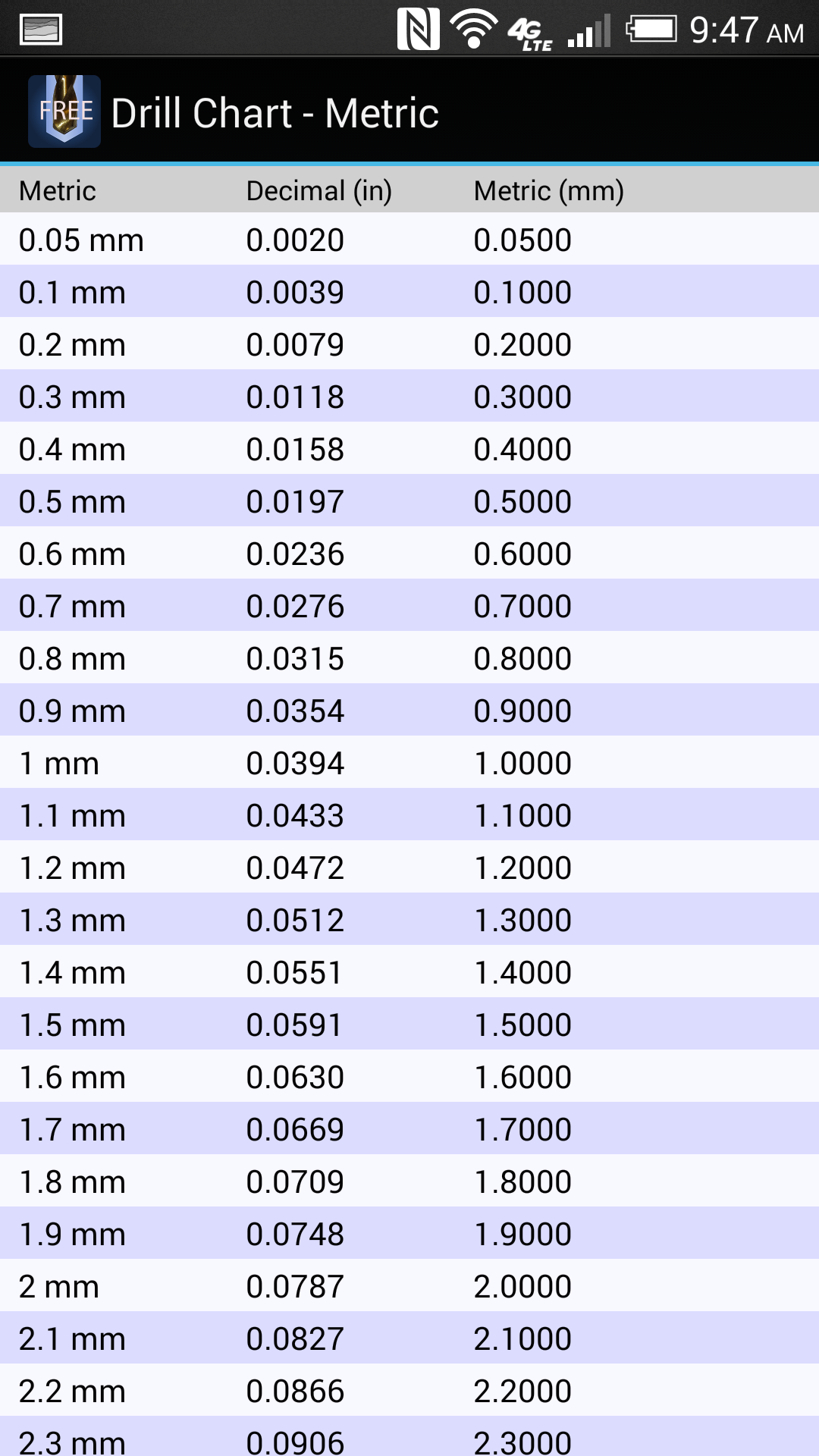 It’s usually located on the ‘head’ of the tool near the drill bit, which is the part that spins. This area is also referred to as a chuck.
 02 mm
02 mm
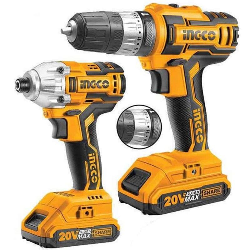 1440
1440 0550
0550 0135
0135 0197
0197