What are the different types of hernias. How are hernias treated. Which surgical techniques are used for hernia repair. What is surgical mesh and how is it used in hernia repair. What are the benefits and risks of using surgical mesh.
Understanding Hernias: Types, Causes, and Prevalence
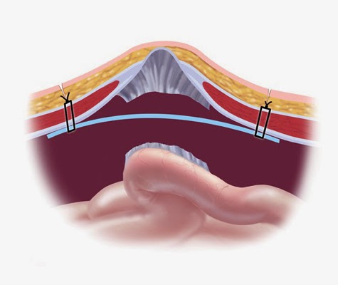
A hernia occurs when an organ, intestine, or fatty tissue protrudes through a weak spot in the surrounding muscle or connective tissue. Most commonly affecting the abdominal wall, hernias can often be visible as an external bulge, particularly when straining or bearing down.
There are several types of hernias, each named based on their location:
- Inguinal: Inner groin
- Femoral: Upper thigh/outer groin
- Incisional: Through an abdominal incision or scar
- Ventral: General abdominal/ventral wall
- Umbilical: Belly button
- Hiatal: Inside the abdomen, along the upper stomach/diaphragm
Hernias typically result from a combination of pressure and a weakness in muscle or connective tissue. While some muscle weaknesses are present at birth, most develop later in life. Factors that can increase abdominal pressure and contribute to hernia formation include obesity, heavy lifting, persistent coughing or sneezing, and chronic constipation or diarrhea. Poor nutrition, smoking, and overexertion can also weaken muscles, increasing the likelihood of hernia development.
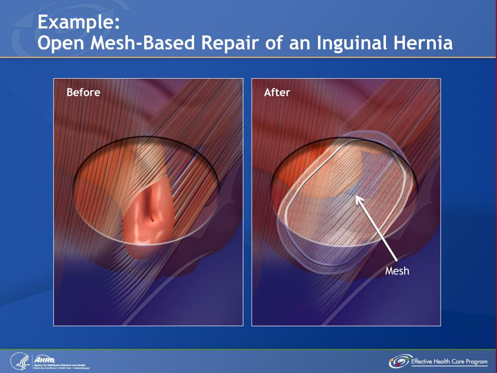
Hernia repairs are among the most common surgical procedures in the United States, with over one million performed annually. Of these, approximately 800,000 are inguinal hernia repairs, highlighting the prevalence of this particular type.
Treatment Options for Hernias: From Watchful Waiting to Surgical Intervention
When it comes to hernia treatment, patients have several options, ranging from non-surgical approaches to various surgical techniques. The choice of treatment depends on the type and severity of the hernia, as well as the patient’s overall health and preferences.
Non-Surgical Approach: Watchful Waiting
For some patients, particularly those with asymptomatic or minimally symptomatic inguinal hernias, watchful waiting may be an appropriate option. This approach involves regular monitoring of the hernia by a surgeon to ensure it’s not growing larger or causing complications. While surgery is the only definitive treatment for hernias, many adult inguinal hernia repairs are considered elective procedures.
Surgical Options for Hernia Repair
When surgical intervention is necessary, there are two main approaches:
- Laparoscopic Repair: This minimally invasive technique involves making several small incisions in the abdomen through which surgical tools are inserted to repair the hernia. Laparoscopic surgery can be performed with or without surgical mesh.
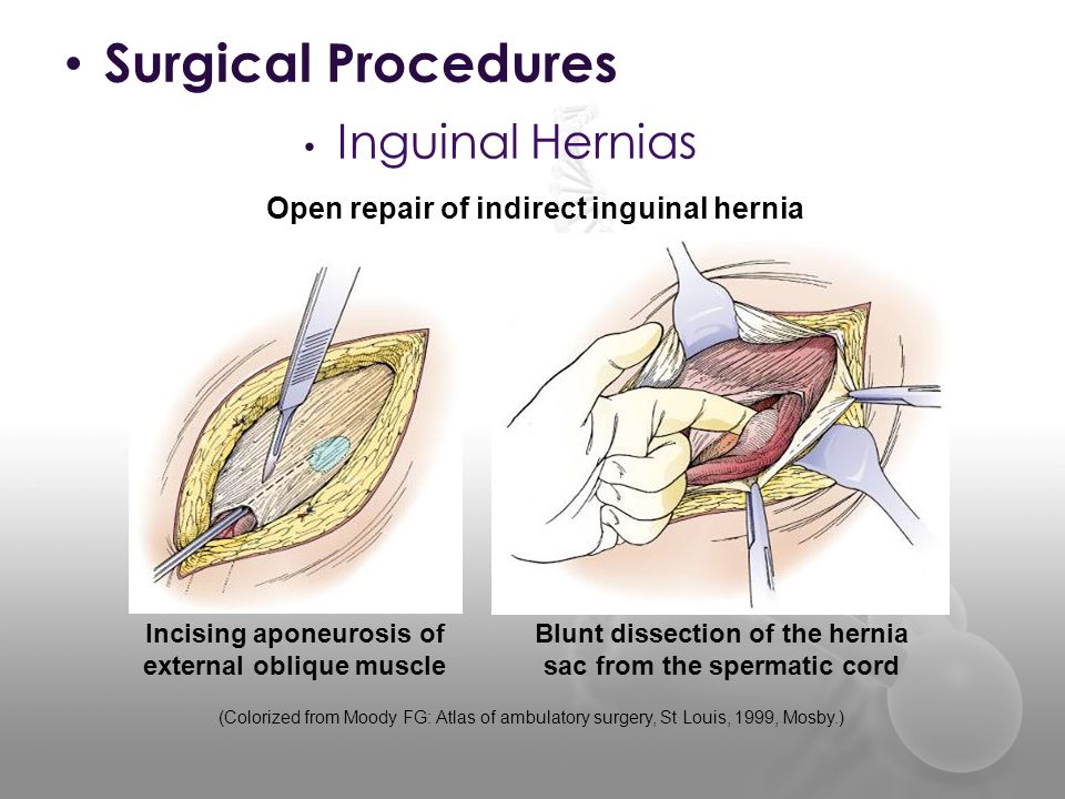
- Open Repair: In this traditional approach, the surgeon makes a single, larger incision near the hernia site to access and repair the weakened muscle area. Open repair can also be performed with or without surgical mesh. When sutures are used without mesh, it’s referred to as primary closure, which is typically used for inguinal hernias in infants, small hernias, or strangulated or infected hernias.
How does the use of surgical mesh impact hernia repair outcomes? Surgical mesh has been increasingly used in hernia repairs since the 1980s due to its ability to strengthen the repair and reduce recurrence rates. By 2000, non-mesh repairs represented less than 10% of groin hernia repair techniques. The use of mesh may also offer benefits such as decreased operative time and potentially faster recovery, although individual recovery times can vary based on hernia type, surgical approach, and patient condition.
Surgical Mesh: Materials, Types, and Applications in Hernia Repair
Surgical mesh is a medical device designed to provide additional support to weakened or damaged tissue. In hernia repair, it serves as a reinforcement to the compromised abdominal wall, helping to prevent hernia recurrence. But what exactly is surgical mesh made of, and what types are available for hernia repair?
Mesh Materials
Surgical mesh can be categorized into two main types based on their source material:
- Synthetic Mesh: Made from man-made materials, synthetic mesh can be further classified into:
- Absorbable: These meshes degrade over time and are eventually absorbed by the body.
- Non-absorbable: These meshes are permanent implants that remain in the body indefinitely.
- Combination: Some meshes incorporate both absorbable and non-absorbable components.
- Biologic Mesh: Derived from animal tissue (such as intestine or skin), these meshes are processed and disinfected to make them suitable for implantation. Biologic meshes are typically absorbable.
Mesh Forms
Synthetic mesh is available in two primary forms:

- Knitted Mesh: This form allows for tissue ingrowth, which can help integrate the mesh with the surrounding tissue.
- Non-knitted Sheet: This form provides a solid barrier and may be preferred in certain applications.
Why is the choice of mesh material and form important? The selection of mesh type can significantly impact the success of the hernia repair and the patient’s post-operative experience. Factors such as the hernia’s location, size, and the patient’s individual characteristics all play a role in determining the most appropriate mesh for each case.
The Impact of Surgical Mesh on Hernia Recurrence Rates
One of the primary reasons for the widespread adoption of surgical mesh in hernia repair is its demonstrated ability to reduce recurrence rates. But how significant is this reduction, and what does the medical literature say about it?
Multiple studies have consistently shown lower hernia recurrence rates when surgical mesh is used compared to non-mesh repair techniques. For instance, inguinal hernia recurrence has been found to be higher with open repair using sutures (primary closure) than with mesh repair.

What are the specific benefits of using surgical mesh in hernia repair?
- Reduced recurrence rates
- Potential for decreased operative time
- Possibly minimized recovery time (although this can vary depending on individual factors)
However, it’s important to note that while mesh repair offers these advantages, there are situations where its use may not be recommended. Patients should engage in thorough discussions with their surgeons to understand their specific circumstances and explore the best options for their hernia repair.
Considerations and Potential Risks of Surgical Mesh in Hernia Repair
While surgical mesh has become a standard component in many hernia repairs due to its benefits, it’s crucial to understand that, like any medical intervention, it comes with potential risks and considerations. What should patients be aware of when considering mesh-based hernia repair?
Potential Complications
Some possible complications associated with surgical mesh in hernia repair include:
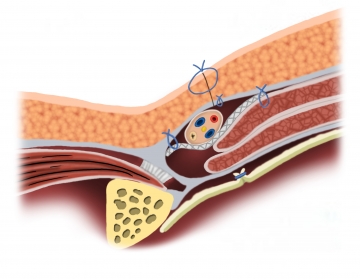
- Infection
- Chronic pain
- Mesh migration
- Adhesion (where the mesh sticks to internal tissues or organs)
- Erosion (where the mesh wears through surrounding tissue)
- Rejection of the mesh by the body
It’s important to note that while these complications can occur, they are not common in all patients. The risk of complications can vary based on factors such as the type of mesh used, the surgical technique, and individual patient characteristics.
Patient-Specific Considerations
How do surgeons determine whether mesh-based repair is appropriate for a particular patient? Several factors come into play:
- Hernia size and location
- Patient’s age and overall health
- Previous surgeries or infections in the area
- Potential for future surgeries in the same area
- Patient’s lifestyle and physical activities
In some cases, surgeons may recommend against using mesh. For example, in cases of infected hernias or when operating on infants, primary closure without mesh might be preferred.
Advances in Hernia Mesh Technology and Future Directions
The field of hernia repair is continually evolving, with ongoing research and development aimed at improving mesh materials and techniques. What are some of the recent advancements and future directions in hernia mesh technology?

Lightweight Meshes
Recent years have seen the development of lightweight meshes, which use less material than traditional meshes. These meshes aim to reduce foreign body reaction while maintaining the strength needed for effective hernia repair. Some potential benefits of lightweight meshes include:
- Reduced chronic pain
- Improved patient comfort
- Potentially faster recovery times
Bioactive Meshes
Researchers are exploring the potential of bioactive meshes, which are designed to actively promote healing and tissue integration. These meshes may incorporate:
- Growth factors to stimulate tissue regeneration
- Antimicrobial agents to reduce the risk of infection
- Anti-inflammatory compounds to minimize post-operative discomfort
3D-Printed Meshes
The advent of 3D printing technology has opened up new possibilities in mesh design. Custom-made, 3D-printed meshes could potentially offer several advantages:
- Tailored to individual patient anatomy
- Optimized pore size and structure for better tissue integration
- Potential for incorporating patient-specific therapeutic agents
How might these advancements shape the future of hernia repair? As these technologies continue to develop and undergo clinical testing, they have the potential to further improve outcomes, reduce complications, and enhance patient satisfaction in hernia repair procedures.

Patient Education and Informed Decision-Making in Hernia Repair
Given the various options available for hernia repair and the potential risks and benefits associated with each, patient education plays a crucial role in ensuring optimal outcomes. How can patients best prepare for discussions with their healthcare providers about hernia repair?
Key Questions for Patients to Ask
When consulting with a surgeon about hernia repair, patients may want to consider asking the following questions:
- What type of hernia do I have, and what are my treatment options?
- Is watchful waiting an appropriate option in my case?
- If surgery is recommended, what type of surgical approach do you suggest and why?
- Will mesh be used in my repair? If so, what type of mesh?
- What are the potential risks and benefits of mesh-based repair versus non-mesh repair in my specific case?
- What is your experience with this type of hernia repair?
- What can I expect in terms of recovery time and potential limitations on activities?
- Are there any specific signs or symptoms I should watch for after surgery?
The Importance of Shared Decision-Making
Why is shared decision-making so crucial in hernia repair? Hernia repair, particularly when it involves the use of surgical mesh, is not a one-size-fits-all procedure. The best approach can vary significantly based on individual factors such as:
- The patient’s overall health and medical history
- The size and location of the hernia
- The patient’s lifestyle and physical activities
- The patient’s personal preferences and risk tolerance
By engaging in open discussions with their healthcare providers, patients can ensure that they fully understand their options, the potential risks and benefits of each approach, and make informed decisions that align with their personal health goals and values.
In conclusion, while surgical mesh has revolutionized hernia repair by reducing recurrence rates and potentially improving other outcomes, it’s essential for patients to be well-informed about all aspects of their treatment options. By understanding the types of hernias, available treatment approaches, the role of surgical mesh, and ongoing advancements in the field, patients can work collaboratively with their healthcare providers to make the best decisions for their individual circumstances.
Hernia Surgical Mesh Implants | FDA
In this website, the FDA describes hernias, the different treatment options to repair hernias and recommendations for patients that are considering surgery for their hernias. The FDA wants to help patients make informed decisions about their health care and to facilitate a discussion between patients and their surgeons.
What is a Hernia?
A hernia occurs when an organ, intestine or fatty tissue squeezes through a hole or a weak spot in the surrounding muscle or connective tissue. Hernias often occur at the abdominal wall. Sometimes a hernia can be visible as an external bulge particularly when straining or bearing down.
Types of Hernias
The most common types of hernias are:
- Inguinal: occurs in the inner groin
- Femoral: occurs in the upper thigh/outer groin
- Incisional: occurs through an incision or scar in the abdomen
- Ventral: occurs in the general abdominal/ventral wall
- Umbilical: occurs at the belly button
- Hiatal: occurs inside the abdomen, along the upper stomach/diaphragm
Causes of Hernias
Most hernias are caused by a combination of pressure and an opening or weakness of muscle or connective tissue. The pressure pushes an organ or tissue through the opening or weak spot. Sometimes the muscle weakness is present at birth but more often it occurs later in life. Anything that causes an increase in abdominal pressure can cause a hernia, including obesity, lifting heavy objects, diarrhea or constipation, or persistent coughing or sneezing. Poor nutrition, smoking, and overexertion can weaken muscles and contribute to the likelihood of a hernia.
Treatment Options for Hernias
Hernia repairs are common—more than one million hernia repairs are performed each year in the U.S. Approximately 800,000 are to repair inguinal hernias and the rest are for other types of hernias.1
- Non-Surgical
- Watchful Waiting – Your surgeon will watch the hernia and make sure that it is not getting larger or causing problems. Although surgery is the only treatment that can repair hernias, many surgical procedures are elective for adult inguinal hernias.
 Watchful waiting is an option for people who do not have complications or symptoms with their hernias, and if recommended by their surgeon.
- Watchful Waiting – Your surgeon will watch the hernia and make sure that it is not getting larger or causing problems. Although surgery is the only treatment that can repair hernias, many surgical procedures are elective for adult inguinal hernias.
- Surgical
- Laparoscopic – The surgeon makes several small incisions in the abdomen that allow surgical tools into the openings to repair the hernia. Laparoscopic surgery can be performed with or without surgical mesh.
- Open Repair – The surgeon makes an incision near the hernia and the weak muscle area is repaired. Open repair can be done with or without surgical mesh. Open repair that uses sutures without mesh is referred to as primary closure. Primary closure is used to repair inguinal hernias in infants, small hernias, strangulated or infected hernias.
Hernias have a high rate of recurrence, and surgeons often use surgical mesh to strengthen the hernia repair and reduce the rate of recurrence. Since the 1980s, there has been an increase in mesh-based hernia repairs—by 2000, non-mesh repairs represented less than 10% of groin hernia repair techniques.
The use of surgical mesh may also improve patient outcomes through decreased operative time and minimized recovery time. However, recovery time depends on the type of hernia, the surgical approach, and the patient’s condition both before and after surgery.
Information found in medical literature has consistently demonstrated a reduced hernia recurrence rate when surgical mesh is used to repair the hernia compared to hernia repair without surgical mesh. For example, inguinal hernia recurrence is higher with open repair using sutures (primary closure) than with mesh repair2.
Despite reduced rates of recurrence, there are situations where the use of surgical mesh for hernia repair may not be recommended. Patients should talk to their surgeons about their specific circumstances and their best options and alternatives for hernia repair.
Surgical Mesh
Surgical mesh is a medical device that is used to provide additional support to weakened or damaged tissue. The majority of surgical mesh devices currently available for use are constructed from synthetic materials or animal tissue.
Surgical mesh made of synthetic materials can be found in knitted mesh or non-knitted sheet forms. The synthetic materials used can be absorbable, non-absorbable or a combination of absorbable and non-absorbable materials.
Animal-derived mesh are made of animal tissue, such as intestine or skin, that has been processed and disinfected to be suitable for use as an implanted device. These animal-derived mesh are absorbable. The majority of tissue used to produce these mesh implants are from a pig (porcine) or cow (bovine) source.
Non-absorbable mesh will remain in the body indefinitely and is considered a permanent implant. It is used to provide permanent reinforcement to the repaired hernia. Absorbable mesh will degrade and lose strength over time. It is not intended to provide long-term reinforcement to the repair site. As the material degrades, new tissue growth is intended to provide strength to the repair.
Hernia Repair Surgery Complications
Based on FDA’s analysis of medical device adverse event reports and of peer-reviewed, scientific literature, the most common adverse events for all surgical repair of hernias—with or without mesh—are pain, infection, hernia recurrence, scar-like tissue that sticks tissues together (adhesion), blockage of the large or small intestine (obstruction), bleeding, abnormal connection between organs, vessels, or intestines (fistula), fluid build-up at the surgical site (seroma), and a hole in neighboring tissues or organs (perforation).
The most common adverse events following hernia repair with mesh are pain, infection, hernia recurrence, adhesion, and bowel obstruction. Some other potential adverse events that can occur following hernia repair with mesh are mesh migration and mesh shrinkage (contraction).
Many complications related to hernia repair with surgical mesh that have been reported to the FDA have been associated with recalled mesh products that are no longer on the market.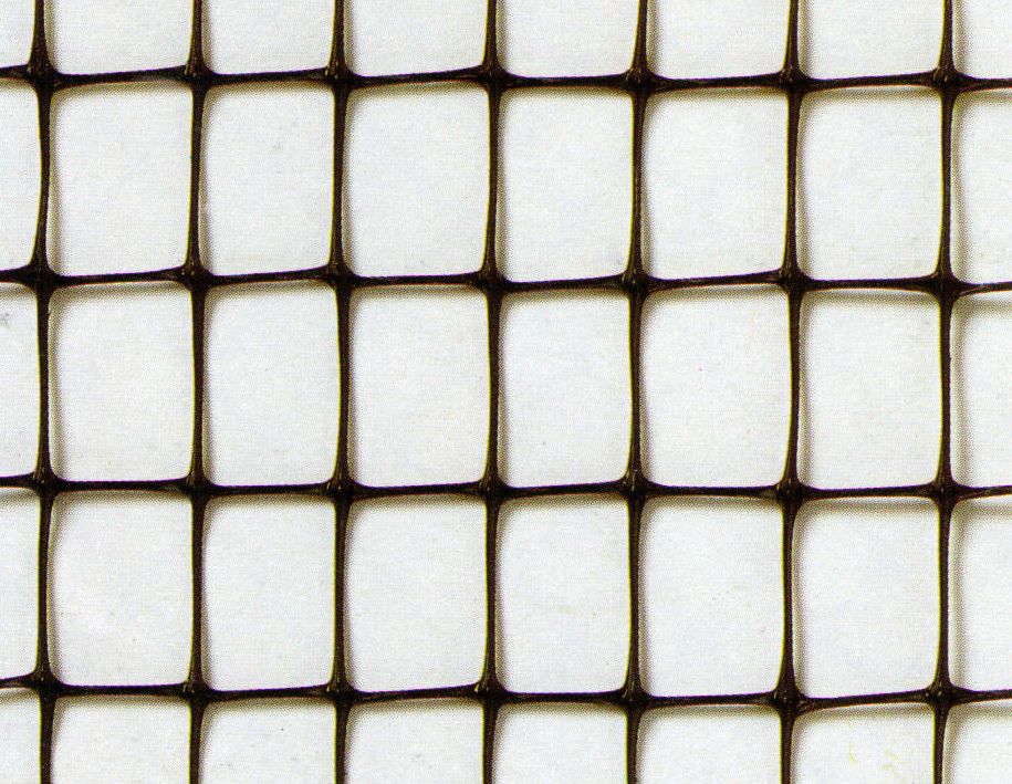 Pain, infection, recurrence, adhesion, obstruction, and perforation are the most common complications associated with recalled mesh. In the FDA’s analysis of medical adverse event reports to the FDA, recalled mesh products were the main cause of bowel perforation and obstruction complications.
Please refer to the recall notices here for more information if you have recalled mesh. For more information on the recalled products, please visit the FDA Medical Device Recall website. Please visit the Medical & Radiation Emitting Device Database to search a specific type of surgical mesh.
If you are unsure about the specific mesh manufacturer and brand used in your surgery and have questions about your hernia repair, contact your surgeon or the facility where your surgery was performed to obtain the information from your medical record.
1Rutkow, I.M. (2003). Demographic and Socieconomic Aspects of Hernia Repair in the United States in 2003. Surgical Clinics of North America; 83(5):1045-51, v-vi.
2. http://www.facs.org/public_info/operation/brochures/hernrep.pdf
Other Resources
About Surgical Mesh | Voices for PFD
What is Surgical Mesh?
Surgical mesh is a fabric netting that is made from animal tissue or synthetic material. Mesh has been used for a long time in surgery and it is safe. There are different types of mesh used for surgery:
- Biological graft mesh—made from the disinfected intestines or the skins of pigs and cows. This type of mesh is absorbable. It, thus dissolves into the body over several months.
- Synthetic dissolvable mesh—made from a soft, suture material woven into fabric. It is also absorbable and goes away after several months.
- Synthetic permanent mesh—made from medical grade plastic fabric, often polypropylene. This type of mesh is not absorbed by the body.
 It is designed for long-term use.
Concerns about mesh side effects do not include surgeries done with biological graft or synthetic dissolvable mesh. The problems relate to the use of synthetic permanent mesh for one specific type of pelvic organ prolapse (POP) mesh surgery. Read on to learn more.
How is Mesh Used to Treat Pelvic Floor Disorders?
Pelvic floor disorders (PFDs) are a group of conditions that affect the pelvic floor. The pelvic floor is the set of muscles and other tissues in the lowest part of the pelvis that support the organs such as the bladder, vagina and rectum. If those muscles and tissues weaken or get damaged, the organs may drop out of the body. When this happens, some women may also leak urine.
Mesh is used to provide short-term or long-term support for weak and damaged body tissues, such as those in the pelvic floor. It helps to reinforce your body tissues. Thus, the type of mesh used depends on your diagnosis and the reason for the surgery:
- Short-term support of tissues—biological graft mesh and synthetic dissolvable mesh are used.

- Long-term support—synthetic permanent mesh provides is used.
Plus, depending upon on your individual situation, the surgeon will determine where and how to place the mesh. And, if permanent or dissolvable mesh is needed.
What PFD Surgeries Require Mesh?
Surgeons use mesh to treat two types of PFDs—stress urinary incontinence (SUI) and pelvic organ prolapse (POP):
- SUI is the leakage of urine with activities, such as laughing, coughing, sneezing, and straining. Mesh is used to help support the bladder or urethra, which is the tube that carries urine out of the body. SUI surgery is typically very successful and often low risk.
- POP is the dropping of the pelvic organs, such as the bladder, intestine, and uterus, caused by loss of normal support of the vagina. During POP surgery, the doctor inserts mesh to reinforce the weak vaginal wall. POP surgery can be done through the:
- Abdomen, called transabdominal
- Vagina, called transvaginal
Thus, for both these conditions, the mesh is placed in the pelvic area to reinforce weakened body tissues. Most women who have these surgeries are happy with the outcomes.
Safety concerns: Many women who had mesh surgery have done well. But, mesh surgeries like all surgeries have risks. And, the risks for the mesh used to treat SUI are not the same as the risk for mesh used for POP repair. Also, there are different risks related to because of where and how the mesh is placed. Plus, the risks vary depending on whether it is permanent or dissolvable mesh.
The recent concerns about mesh risks are linked to transvaginal POP surgery only. We now know that the risk of complications for transvaginal repair can be high. After this particular surgery, many women report serious complications. For example, infection, pain, urinary problems, vaginal scarring, and urinary incontinence. Plus, in some women, the mesh dislodged and moved into the surrounding tissue—this mesh may erode into those tissues and damage organs. Because of this, the Food and Drug Administration is requiring mesh makers to conduct further tests. These companies must provide stronger proof on the safety and effectiveness of this type of mesh device.
Talk with your doctor about risks before the surgery. And, make sure you understand clearly any mesh surgery your doctor discusses. Ask questions, take notes and consider bringing along a friend or family member to listen as well.
What Should I Ask My Doctor Before Mesh Surgery?
Before you have mesh surgery, talk with your doctor about the following five things:
- First, find out if you are a good candidate for mesh surgery. Women who smoke or have poorly controlled diabetes are at a higher risk for complications. Thus, they may not be good candidates for a mesh surgery.
- Also ask about the specific surgery. Complications for SUI mesh surgery and POP transabdominal are low. Risks are higher for POP transvaginal surgeries.
- Talk with your doctor about the benefits. Request a list of all potential risks and complications.

- Discuss quality of life issues with your doctor.
- Find out about other treatment options. Assess the risk and benefits of the surgery based on those quality of life factors.
Also, seek a second opinion and ask to go over the same information with that surgeon.
Should I Get the Mesh Removed?
Most women who have mesh surgery recover well and find relief of their symptoms. It is rare that a woman who has SUI mesh surgery or POP transabdominal surgery needs to have the mesh removed. Women who had transvaginal POP surgery, however, may need to consider mesh removal surgery.
Transvaginal POP surgery uses a permanent mesh material. Over time, body tissues grow into the holes of the mesh to help hold it in place. If the mesh has moved out of place, it may be embedded in other body tissues and pelvic organs. If the side effects of the mesh device are so severe that they outweigh the benefits, the doctor may ask you about mesh removal surgery.
Surgery to remove transvaginal mesh is very complex. Mesh removal surgery requires a highly trained surgeon with special knowledge of the pelvic anatomy and POP surgery. During the surgery, the doctor attempts to remove as much of the mesh as possible. Plus, damaged tissue is repaired. For many women, more than one surgery is required to fully repair the pelvic area.
If you have serious complications related to the mesh, talk with your surgeon about the need to have the mesh devise removed. The discussion will require you to weigh the impact of the side effects on your quality of life with the risks associated with the removal surgery. It is a hard decision. Take time, to review the risks and benefits with your surgeon.
Learn More About the Benefits and Risks of Mesh Surgeries
Download the fact sheet about the surgery your doctor recommends. Take it with you to your appointment to help review the risks. Ask the doctor about the benefits and risks that might apply to you based on your individual diagnosis and health status.
Read More About Surgical Mesh
Surgical Mesh Types | TheLawFirm.com
Bard Davol, Inc., is a gigantic medical-supplies business. The corporation is based in Providence, Rhode Island, and has been manufacturing and selling medical and surgical supplies since 1874. So the company has quite a lot of experience developing, testing, marketing, and selling products for medical and surgical procedures.
As one of the leading manufacturers of hernia mesh devices, Bard Davol, Inc., knows something about the potential health hazards of these products. So let’s let Bard Davol, Inc., take the lead in explaining how its Visilex hernia mesh can pose serious health issues in the patients in who it has been surgically implanted.
Here’s what Bard Davol’s own website says about the possible “adverse reactions” to its Visilex hernia mesh:
Adverse Reactions associated with surgical mesh may include but are not limited to seroma, adhesion, hematoma, pain, infection, inflammation, extrusion, erosion, migration, fistula formation and srecurrence of the hernia or soft tissue defect.
That sounds pretty serious, Bard Davol. Let’s go through those one by one.
Seroma
A seroma is a pocket of clear fluid that can develop in the body after a surgical procedure. Most of that fluid is blood plasma.
Seromas are often harmless, but they can linger in the body for as long as years, and can harden into little nodes, which sometimes require surgical removal.
Often, seromas are breeding grounds for the bacteria that can cause infection. If a seroma ruptures, infectious bacteria can spill out into the body cavity, where they can cause serious health problems.
Strike one against the Bard Davol Visilex hernia mesh.
Adhesion
When Bard Davol, Inc., refers to the Visilex having an “adhesion” problem, they’re making a serious health hazard sound no worse than the roll of tape you keep in your office drawer.
All hernia mesh devices can cause complications by adhering to internal tissues and organs. The devices can dissolve into body tissues, effectively “melting” into them. When that happens, hernia mesh can be impossible to remove, and it can cause inflammation and infection (more on those subjects below).
Hernia mesh adhesion is a nasty business.
Strike two against the Bard Davol Visilex hernia mesh.
Hematoma
“Hematoma” is the medical term for bruising. Hematomas develop when blood vessels rupture, releasing blood into the body, where it collects.
In most cases, hematomas heal themselves as the blood is slowly reabsorbed into the body. In most cases, hematomas are tender and painful. In some cases, hematomas can restrict movement and can cause lumps which may require surgical removal.
Strike three against the Bard Davol Visilex hernia mesh. Inning over.
Pain
No surgical procedure is enjoyable. We expect surgery itself to cause discomfort and pain. But when a surgically implanted device itself causes pain, that’s a problem. On the advice of our doctors, we undergo surgery to remove pain, not to increase the likelihood of pain.
Strike four against the Bard Davol Visilex hernia mesh.
Infection
The “adhesion” mentioned above is the main cause of infection with the Visilex hernia mesh. The Visilex can get absorbed into body organs and tissues – it actually becomes a part of the body, and is often impossible to remove, even with the most advanced surgical techniques.
Since, of course, the Visilex is not a part of the body itself – it’s made of polypropylene plastic – the body regards it as a foreign entity, and summons all the defenses in the immune system to combat it. That’s when infection can set in – just like when you ignore that splinter in your heel for too long.
The Visilex is supposed to help, not hurt.
Strike five against the Bard Davol Visilex hernia mesh.
Inflammation
Inflammation is less serious than infection, but that doesn’t mean it’s any less painful. An inflamed organ or tissue can cause serious pain or discomfort.
Strike six against the Bard Davol Visilex hernia mesh. Another side retired.
Extrusion
“Extrusion,” in this case, means “the tissues of your body may deform and get squeezed through the tiny little holes in the Visilex hernia mesh, causing you a great deal of pain.”
As the polypropylene plastic that makes up the Visilex hernia mesh shrinks, deforms, and dissolves, so do the tiny gaps in the mesh. Body tissue can get pressed and squeezed – extruded, that is – through those tiny gaps.
Imagine taking a piece of chicken wire and pressing it against your thigh. Now press harder. Harder. Harder. That hurts pretty bad, right? That’s exactly what’s happening, on a microscopic scale, during the process of “extrusion” with the Visilex hernia mesh.
Strike seven against the Bard Davol Visilex hernia mesh.
Erosion
“Erosion” sounds like a natural process. River beds erode. Cliffsides erode. Even the Grand Canyon was formed by erosion.
Yet the erosion associated with the Visilex hernia mesh is anything but natural. In this case, “erosion” means that the plastic that comprises the Visilex mesh can actually dissolve and melt into body tissue. Patients who have been implanted with the Visilex actually have melted – excuse us, eroded – plastic inside their bodies.
We believe that melted plastic has no business being inside the body.
Strike eight against the Bard Davol Visilex hernia mesh.
Migration
Oh, how nice – migration. Like Canada geese and monarch butterflies during the change of seasons.
The thing is, though, that, in order for a hernia mesh to do its job, it has to stay in one place. The Visilex hernia mesh is supposed to keep organs and tissues in place at the site of a surgical procedure. But if the Visilex decides to “migrate” to another part of the body, it can cause major problems. First, it’s not present at the site where it’s supposed to do its job of keeping organs in place. Second, it can get loose in the body, where it can get tangled up with blood vessels, organs, and tissues, thereby causing all kinds of unpredictable and potentially life-threatening complications.
Strike nine against the Bard Davol Visilex hernia mesh. Three innings have passed, and Team Visilex hasn’t even managed a walk or a foul tip.
Fistula Formation
A fistula is an unnatural “passageway” that forms between two bodily organs, or between an organ and the outside world. Think of the formation of a fistula in the body like the construction of a hallway between two rooms in the house – except it’s a hallway that no one wanted, that serves no purpose, and that can compromise the structural integrity of the whole building.
Fistulas can easily develop infections. Fistulas can cause swelling, discomfort, and pain. Fistulas can require surgery. Depending on where they are located, fistulas can be fatal.
Strike ten against the Bard Davol Visilex hernia mesh.
Recurrence Of The Hernia Or Soft Tissue Defect
Here’s the worst problem of all with the Visilex hernia mesh: It may very well cause the problem that it was supposed to solve.
The Visilex hernia mesh – after possibly causing infection, erosion, fistulas, and all these other health complication – may in fact wind up serving absolutely no purpose whatsoever. It can cause the hernia is was supposed to contain.
There could not be a more pointless, negative outcome.
Strike eleven against the Bard Davol Visilex hernia mesh. In fact, let’s call it strike two million. There’s little that’s good about the Visilex hernia mesh, but there’s a lot that’s very, very bad.
If you’ve had a Visilex hernia mesh surgically implanted, you may be at risk – and you may be entitled to significant financial compensation. To find out what you can do about it, contact TheLawFirm.com.
Meshing Your Geometry: When to Use the Various Element Types
In a previous blog entry, we introduced meshing considerations for linear static problems. One of the key concepts there was the idea of mesh convergence — as you refine the mesh, the solution will become more accurate. In this post, we will delve deeper into how to choose an appropriate mesh to start your mesh convergence studies for linear static finite element problems.
What Are the Different Element Types
As we saw earlier, there are four different 3D element types — tets, bricks, prisms, and pyramids:
These four elements can be used, in various combinations, to mesh any 3D model. (For 2D models, you have triangular and quadrilateral elements available. We won’t discuss 2D very much here, since it is a logical subset of 3D that doesn’t require much extra explanation.) What we haven’t spoken in-depth about yet is why you would want to use these various elements.
Why and When to Use the Elements
Tetrahedral elements are the default element type for most physics within COMSOL Multiphysics. Tetrahedra are also known as a simplex, which simply means that any 3D volume, regardless of shape or topology, can be meshed with tets. They are also the only kind of elements that can be used with adaptive mesh refinement. For these reasons, tets can usually be your first choice.
The other three element types (bricks, prisms, and pyramids) should be used only when it is motivated to do so. It is first worth noting that these elements will not always be able to mesh a particular geometry. The meshing algorithm usually requires some more user input to create such a mesh, so before going through this effort, you need to ask yourself if it is motivated. Here, we will talk about the motivations behind using brick and prism elements. The pyramids are only used when creating a transition in the mesh between bricks and tets.
It is worth giving a bit of historical context. The mathematics behind the finite element method was developed well before the first electronic computers. The first computers to run finite element programs were full of vacuum tubes and hand-wired circuitry, and although the invention of transistors led to huge improvements, even the supercomputers from 25 years ago had about the same clock speed as today’s fashion accessories.
Some of the first finite element problems solved were in the area of structural mechanics, and the early programs were written for computers with very little memory. Thus, first-order elements (often with special integration schemes) were used to save memory and clock cycles. However, first-order tetrahedral elements have significant issues for structural mechanics problems, whereas first-order bricks can give accurate results.
As a legacy of these older codes, many structural engineers will still prefer bricks over tets. In fact, the second order tetrahedral element used for structural mechanics problems in the COMSOL software will give accurate results, albeit with different memory requirements and solution times from brick elements.
The primary motivation in COMSOL Multiphysics for using brick and prism elements is that they can significantly reduce the number of elements in the mesh. These elements can have very high aspect ratios (the ratio of longest to shortest edge), whereas the algorithm used to create a tet mesh will try to keep the aspect ratio close to unity. It is reasonable to use high aspect ratio brick and prism elements when you know that the solution varies gradually in certain directions or if you are not very interested in accurate results in those regions because you already know the interesting results are elsewhere in the model.
Meshing Example 1: Wheel Rim
Consider the example of a wheel rim, shown below.
The mesh on the left is composed only of tets, while the mesh on the right has tets (green), bricks (blue), and prisms (pink), as well as pyramids to transition between these elements. The mixed mesh uses smaller tets around the holes and corners, where we expect higher stresses. Bricks and prisms are used in the spokes and around the rim. Neither the rim nor the spokes will carry peak stresses (at least under a static load), and we can safely assume a relatively slow variation of the stresses in these regions.
The tet mesh has about 145,000 elements and around 730,000 degrees of freedom. The mixed mesh has close to 78,000 elements and roughly 414,000 degrees of freedom, taking about half as much time and memory to solve. The mixed mesh does take significant user interaction to set up, while the tet mesh requires essentially no user effort.
Note that there is not a direct relationship between degrees of freedom and memory used to solve the problem. This is because the different element types have different computational requirements. A second-order tet has 10 nodes per element, while a second-order brick has 27. This means that the individual element matrices are larger, and the corresponding system matrices will be denser, when using a brick mesh. The memory (and time) needed to compute a solution depends upon the number of degrees of freedom solved for, as well as the average connectivity of the nodes, and other factors.
Meshing Example 2: Loaded Spring
Another example is shown below. This time, it’s a structural analysis of a loaded spring. Since the deformation is quite uniform along the length of the helix of the spring, it makes sense to have a mesh that describes the overall shape and cross section, but relatively stretched elements along the length of the wire. The prism mesh has 504 elements with 9526 degrees of freedom, and the tet mesh has 3652 elements with 23,434 degrees of freedom. So although the number of elements is quite different, the number of degrees of freedom is less so.
Meshing Example 3: Material on a Wafer
The other significant motivation for using brick and prism elements is when the geometry contains very thin structures in one direction, such as an epitaxial layer of material on a wafer, a stamped sheet metal part, or a sandwiched composite.
For example, let’s look at the figure below of a thin trace of material patterned onto a substrate. The tet mesh has very small elements in the trace, whereas the prism mesh is composed of thin elements in this region. Whenever your geometry has layers that are about 10-3 or so times thinner than the largest dimension of the part, the usage of bricks and prisms becomes very highly motivated.
Additional Examples
It is also worth pointing out that the COMSOL software offers many boundary conditions that can be used in lieu of explicitly modeling thin layers of materials. For example, in electromagnetics, the following four tutorial models consider thin layers of material with relatively high and low conductivity, and relatively high and low permeability:
Similar types of boundary conditions exist in most of the physics interfaces. Usage of these types of boundary conditions will avoid the need to mesh such thin layers entirely.
Lastly, the above comments apply only to linear static finite element problems. Different meshing techniques are needed for nonlinear static problems, or if we are modeling time-domain or frequency-domain phenomena.
Concluding Thoughts
To summarize, here is what you should keep in mind when starting your meshing of linear static problems:
- Use tets if you can; they require the least user interaction and support adaptive mesh refinement
- If you know the solution varies slowly in one or more directions, use bricks or prisms with high aspect ratios in those regions
- If the geometry contains thin layers of material, use bricks or prisms or consider using a boundary condition instead
- Always perform a mesh refinement study and monitor the memory requirements and convergence of the solution as you refine the mesh
Further Reading
Surgical Mesh | Encyclopedia.com
Definition
Demographics
Description
Mesh Used for Tissue Support
Mesh Used for Hernia Repair
Risks Associated with Surgical Mesh
Surgical mesh is a sterile woven piece of netting that is used in surgical procedures to help repair sites of surgical incision, tissue herniation, or to provide support to internal parts of the body.
Surgical mesh is used in many different types of surgical procedures. Hernia repair is one of the most frequently performed general surgeries world wide, and usually involves the use of surgical mesh. Mesh is also used to assist in surgical correction of urinary incontinence, uterine suspension, vertebral reconstruction, tissue reconstruction, vaginal prolapse, and provides support for devices implanted to support the heart.
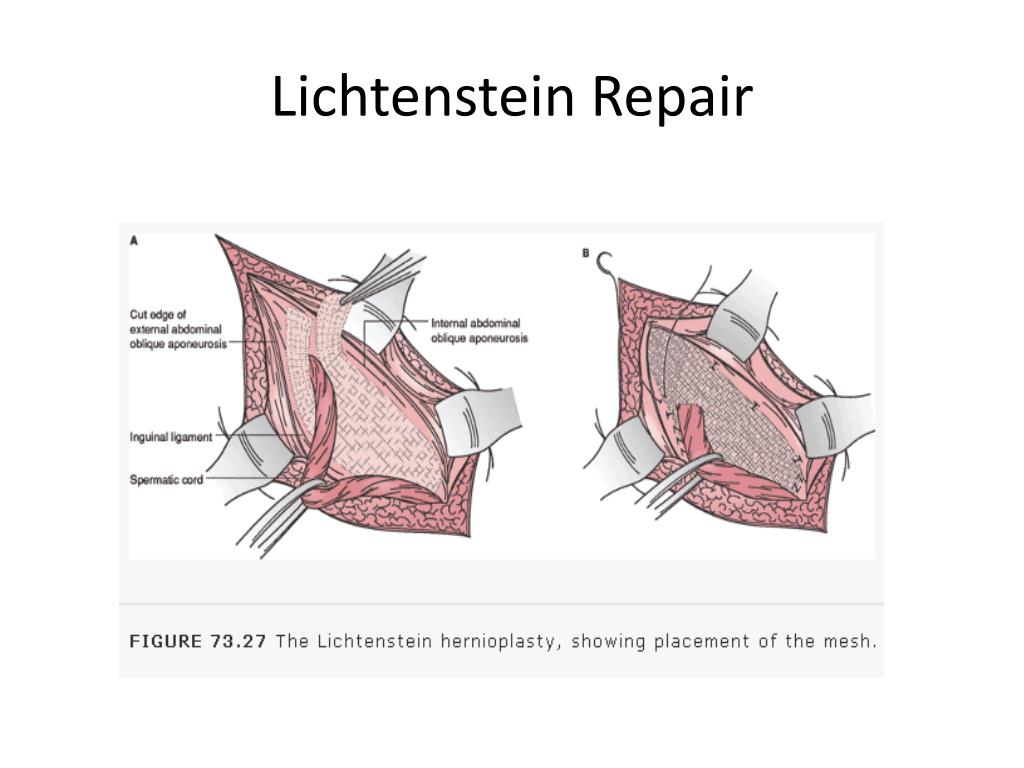
Surgical mesh can be used in many different surgical procedures to provide wound closure or support for internal body parts. Also known as a patch or screen, surgical mesh is implanted in the body for repair or reinforcement. Surgical mesh may be absorbable or non-absorbable. Some types of repair procedures using surgical mesh may also be called a “Lichtenstein Repair,” because of a surgeon named Irving Lichtenstein whose influence in the medical field increased the widespread use of surgical mesh. A Lichtenstein Repair is specifically a flat piece of surgical mesh used as a patch placed on top of a tissue defect.
Surgical mesh is usually a sterile, woven material made of a type of synthetic plastic. Surgical mesh can be made of various different types of synthetic material, such as Gore-Tex, polyprolene, or knitted polyester. Mesh is very sturdy and strong, yet extremely thin. It is soft and flexible to allow it to easily conform to the movement of the body. Surgical mesh is available in various measurements and can be cut to size for each surgical application. Depending on the type of repair that is needed, a patch of mesh is placed under, over, or within a defect in the body and sewn in place by a few sutures. The mesh acts as a type of scaffold for the body tissue that grows around and into the mesh. Mesh is also used like a sling to support internal body parts and hold them in place.
Once inserted, mesh is eventually incorporated into the surrounding tissue as if it is part of the body. For this reason, mesh is considered a tension-free type of repair, as opposed to sutures. Sutures hold flesh together through the tension they create by pulling tissues together to close a wound. Because sutures create tension in the tissue they repair, too much movement early on in the recovery period after surgery can re-open the repair site and cause internal bleeding. Mesh is different in that it does not rely on tension to hold tissue together. Rather the mesh itself fills the wound and allows tissue to grow into and around it. Patients in which surgical mesh has been used may resume activity much sooner after the surgical procedure than is usually seen with tension repair techniques such as sutures. Surgical mesh may be used in the form of a patch that goes under or over a weakness in body tissues, or a plug that goes inside a hole in the tissue. The patient cannot feel the internal mesh, and is able to move freely.
Surgical mesh may be used to help physically support body tissues that are weak or damaged in some way. One example of a procedure that may benefit from mesh in this way is uterine suspension. Uterine suspension is necessary when the uterus is tipped out of its normal position and causes medical complications. Uterine suspension is performed to put the uterus back into its normal position. Surgical mesh may be used as a sling to support the uterus and hold it in place. A second example of mesh used for tissue support is as a sling for the urethra in some types of urinary incontinence where the urethra has fallen out of its normal position. In surgery done for urinary incontinence, a sling is put in place to lift the urethra back into its normal position and create a type of pressure that helps prevent the incontinence. A mesh sling may be used and attached to the abdominal wall, where the body tissue will grow around and into it to provide strength and support.
Hernia repair is the most common use for surgical mesh. A hernia is a protrusion of body tissues through a defect in a muscle or other containing body parts. Mesh may be used to repair the defect that allowed the herniation of body tissue. Hernias used to be commonly repaired using sutures and other types of tension-based tissue closure techniques. However, sutures do not allow for free movement as soon after the surgery. Sutures also create a higher post-operative intra-abdominal pressure and consequent breathing problems than mesh. Sutures are associated with a higher rate of hernia recurrence than mesh. Mesh hernia repair also causes less pain after surgery than suture repair. Mesh hernia repair clearly has many advantages over hernia repair using sutures.
Almost all hernia repairs are performed today using tension-free surgical mesh. Polyprolene is one of the most commonly used synthetic meshes in hernia repair, with each type of mesh material having advantages and disadvantages for hernia repair. Some hernia repair techniques using mesh include the Lichtenstien Repair where mesh is placed over the defect in the tissue, the Kugel Method where mesh is placed behind the defect, and the Prolene Hernia System where two
KEY TERMS
Adhesions— Scar tissue.
Intra-abdominal Pressure— The pressure present in the abdominal cavity that affects the pressure on the diaphragm and the ability to breathe easily.
Prolapse— A condition where the organs fall out of their normal location in the body.
Sutures— Stiches that are used in surgical procedures to bring two pieces of flesh together or close a wound.
Urinary Incontinence— Disorder where urination is uncontrolled and involuntary.
Uterine Suspension— Procedure that places a sling under the uterus and holds it in place.
Vertebral Reconstruction— Procedure for reconstruction and support of the vertebrae of the skeletal system.
layers of mesh are placed around the defect, one behind and one over the defect. Another method of mesh-based hernia repair is the Plug and Patch Method, where mesh is placed like a plug into the tissue defect and then covered over the top with another mesh patch. Hernia repairs using mesh may be done as same day surgery using only local anesthesia. Because surgical mesh is a type of tension-free repair, patients can resume normal physical activity much sooner after the operation.
While the use of surgical mesh has many advantages over other techniques, it is also associated with risk of some medical complications. One of the greatest risks of the use of surgical mesh is mesh infection. Mesh infections tend to be resistant to wound care techniques and antibiotics, and are generally removed upon discovery. Removal of infected mesh necessittates a new surgical procedure and the replacement of the mesh with a new repair. Surgical mesh may also cause tissue inflammation, which can be painful. Mesh may also cause adhesions, or scar tissue. Adhesions sometimes cause medical problems in the surrounding area. For example, adhesions in the abdominal cavity may cause obstruction of the bowels, and adhesions in the pelvic region may contribute to infertility in females. All types of hernia repair are associated with the risk of hernia recurrence, the protrusion of tissue through the repaired defect from failure of the mesh or suture repair. Mesh repairs have a lower risk of hernia recurrence than sutures.
Resources
BOOKS
Kumar, Vinay, Nelson Fausto, and Abul Abbas. Robbins & Cotran: Pathologic Basis of Disease, Seventh Edition. Saunders, Elsevier, 2005.
PERIODICALS
Burger, J. W. A., R. W. Luijendijk, W. Hop, J. A. Halm, E. G. Verdaasdonk, J. Jeekel. “Long-term Follow-up of a Randomized Controlled Trial of Suture Versus Mesh Repair of Incisional Hernia.” Ann Surg 240(4):578-585, 2004.
Frey, D. M., A. Wildisen, C. T. Hamel, M. Zuber, D. Oertli, J. Metzger. “Randomized Clinical Trial of Lichtenstein’s Operation Versus Mesh Plug for Inguinal Hernia Repair.” Br J Surg. 2007;94:36–41.
OTHER
“Health Adhesions, General and After Surgery.” eMedicine. October 16, 2005. http://www.emedicinehealth.com/adhesions_general_and_after_surgery/article_em.htm [Accessed April 15, 2008].
Maria Basile, PhD
All there is to know about different mesh types in CFD!
1. Grid/Mesh
A mesh divides a geometry into many elements. These are used by the CFD solver to construct control volumes.
Terminology:
• Cell = control volume into which domain is broken up.
• Node = grid point.
• Cell centre = centre of a cell.
• Edge = boundary of a face.
• Face = boundary of a cell.
• Zone = grouping of nodes, faces, cells
• Domain = group of node, face and cell zones.
Points to consider when generating a mesh are:
• Mesh resolution
• Type of mesh
• Computer resources
The shapes of control volumes depend on the capabilities of the solver. Structured-grid codes use quadrilaterals in 2D and hexahedrons in 3D flows. Unstructured-grid solvers often use triangles (2D) or tetrahedron (3D), but newer codes can use arbitrary polyhedrons.
2. Grid Structure
The purpose of the mesh generator is to decompose the flow domain into control volumes.
The primary outputs are:
• cell vertices
• connectivity information
Precisely where the nodes are relative to the vertices depends on whether the solver uses, for example, cell-centred or cell-vertex storage. Further complexity is introduced if a staggered velocity grid is employed.
3. Grid Types
1) Structured Grids:
a) Cartesian
b) Curvilinear
Grids can be Cartesian or curvilinear (usually body-fitting). In the former, grid lines are always parallel to the coordinate axes. In the latter, coordinate surfaces are curved to fit boundaries. There is an alternative division into orthogonal and non-orthogonal grids. In orthogonal grids (for example, Cartesian or polar meshes) all grid lines cross at 90º. Some flows can be treated as axisymmetric, and in these cases, the flow equations can be expressed in terms of polar coordinates (r,θ), rather than Cartesian coordinates (x,y), with minor modifications.
2) Block-structured Grids:
a) Matching
b) Non-matching
c) Chimera (composite)
In multi-block structured grids the domain is decomposed into a small number of regions, in each of which the mesh is structured (i.e. cells can be indexed by (i,j,k)). A common arrangement is that grid lines match at the interface between two blocks, so that there are cell vertices that are common to two blocks i.e. matching cells. In some cases, the cell counts do not match at the interface i.e. non-matching cells. Non-matching cells (which could be 2 to 1, 3 to 2, …) should be avoided as much as possible as they tend to increase the computational time. Some solvers also allow overlapping blocks (i.e. chimera grids) where cell vertices do not align. Interpolation is then needed at the boundaries of blocks.
Generally, multiple blocks are useful in maintaining a structured grid configuration around complex boundaries. There are no hard and fast rules, but it is generally desirable to avoid sharp changes in grid direction (which lead to lower accuracy) in important and rapidly changing regions of the flow, such as near solid boundaries. One should also strive to minimise the non-orthogonality of the grid.
3) Unstructured Grids:
a) Triangular (tetrahedral)
b) Quadrilateral (hexahedral)
c) Polygon (polyhedral)
d) Hybrid
Unstructured meshes can accommodate completely arbitrary geometries. However, there are significant penalties to be paid for this flexibility, both in terms of the connectivity data structures and solution algorithms. Grid generators and plotting routines for such meshes are also very complex.
4) Tri/Tet vs. Quad/Hex Meshes
• For flow-aligned problems:
– Quad/hex meshes can provide higher quality solutions with fewer cells/nodes than a comparable tri/tet mesh.
– Quad/hex meshes show reduced numerical diffusion when the mesh is aligned with the flow.
– It does require more effort to generate a quad/hex mesh.
• For complex geometries:
– It would be impractical to generate a structured (flow-aligned) hex mesh.
– You can save meshing effort by using a tri/tet mesh or hybrid mesh which are quicker to generate.
• Flow, however, is generally not aligned with the mesh.
• Hybrid meshes typically combine tri/tet elements with other elements in selected regions
– For example, use wedge/prism elements to resolve boundary layers.
– More efficient and accurate than tri/tet alone.
Mesh Types — Axom documentation
The underlying, concrete, representation of the constituent Geometry
and Topology of a mesh is the key defining charachteristic
used in classifying a mesh into the different Mesh Types.
The Geometry and Topology of a mesh is specified in one of the
following three representations:
The possible representation combinations of the constituent Geometry and
Topology comprising a mesh define a taxonomy of Mesh Types
summarized in the table below.
A brief overview of the distinct characteristics of each of the Mesh Types
is provided in the following sections.
Structured Mesh
A Structured Mesh discretization is characterized by its ordered,
regular, Topology. A Structured Mesh divides the computational
domain into Cells that are logically arranged on a regular grid. The
regular grid topology allows for the constituent Nodes, Cells
and Faces of the mesh to be identified using an IJK ordering scheme.
Numbering and Ordering Conventions in a Structured Mesh
The IJK ordering scheme employs indices along each dimension, typically
using the letters i,j,k for the 1st, 2nd and 3rd dimension respectively.
The IJK indices can be thought of as counters. Each index counts the number
of Nodes or Cells along a given dimension. As noted in
the general Mesh Representation section, the constituent entities of
the mesh Topology are associated with a unique index.
Therefore, a convention needs to be established for mapping the IJK indices to
the corresponding unique index and vice-versa.
The general convention and what Mint employs is the following:
- All Nodes and Cells of a Structured Mesh are indexed
first along the I-direction, then along the J-direction and last along
the K-direction. - Likewise, the Faces of a Structured Mesh are indexed by first
counting the Faces of each of the Cells along the
I-direction (I-Faces), then the J-direction (J-Faces) and
last the K-direction (K-Faces).
One of the important advantages of a Structured Mesh representation is
that the constituent Topology of the mesh is implicit. This enables
a convenient way for computing the Connectivity information
automatically without the need to store this information explicitly. For example,
an interior 2D cell (i.e., not at a boundary) located at \(C=(i,j)\),
will always have four face neighbors given by the following indices:
- \(N_0=(i-1,j)\),
- \(N_1=(i+1,j)\),
- \(N_2=(i,j-1)\) and
- \(N_3=(i,j+1)\)
Notably, the neighboring information follows directly from the IJK ordering
scheme and therefore does not need to be stored explicitly.
In addition to the convenience of having automatic Connectivity, the
IJK ordering of a Structured Mesh offers one other important advantage
over an Unstructured Mesh discretization. The IJK ordering
results in coefficient matrices that are banded. This enables the use of
specialized algebraic solvers that rely on the banded structure of the matrix
that are generally more efficient.
While a Structured Mesh discretization offers several advantages, there
are some notable tradeoffs and considerations. Chief among them,
is the implied restriction imposed by the regular topology of the
Structured Mesh. Namely, the number of Nodes and Cells on
opposite sides must be matching. This requirement makes local refinement
less effective, since grid lines need to span across the entire range along
a given dimension. Moreover, meshing of complex geometries, consisting of
sharp features, is complicated and can lead to degenerate Cells that can be
problematic in the computation. These shortcomings are alleviated to an extent
using a block-structured meshing strategy and/or patch-based AMR, however
the fundamental limitations still persist.
All Structured Mesh types have implicit Topology. However, depending
on the underlying, concrete representation of the consituent mesh
Geometry, a Structured Mesh is distinguished into three
subtypes:
- Curvilinear Mesh,
- Rectilinear Mesh, and,
- Uniform Mesh
The key characteristics of each of theses types is discussed in more detail in
the following sections.
Curvilinear Mesh
The Curvilinear Mesh, shown in Fig. 8, is
logically a regular mesh, however in contrast to the Rectilinear Mesh
and Uniform Mesh, the Nodes of a Curvilinear Mesh are not
placed along the Cartesian grid lines. Instead, the equations of the governing
PDE are transformed from the Cartesian coordinates to a new coordinate system,
called a curvilinear coordinate system. Consequently, the Topology of
a Curvilinear Mesh is implicit, however its Geometry, given
by the constituent Nodes of the mesh, is explicit.
Fig. 8 Sample Curvilinear Mesh example.
The mapping of coordinates to the curvilinear coordinate system
facilitates the use of structured meshes for bodies of arbitrary shape. Note,
the axes defining the curvilinear coordinate system do not need to be straight
lines. They can be curves and align with the contours of a solid body. For this
reason, the resulting Curvilinear Mesh is often called a mapped mesh or
body-fitted mesh.
See the Tutorial for an example that demonstrates how to
Create a Curvilinear Mesh.
Rectilinear Mesh
A Rectilinear Mesh, depicted in Fig. 9,
divides the computational domain into a set of rectangular Cells,
arranged on a regular lattice. However, in contrast to the
Curvilinear Mesh, the Geometry of the mesh is not mapped to a
different coordinate system. Instead, the rows and columns of Nodes
comprising a Rectilinear Mesh are parallel to the axis of the Cartesian
coordinate system. Due to this restriction, the geometric domain and resulting
mesh are always rectangular.
Fig. 9 Sample Rectilinear Mesh example.
The Topology of a Rectilinear Mesh is implicit, however its
constituent Geometry is semi-implicit. Although, the
Nodes are aligned with the Cartesian coordinate axis, the spacing
between adjacent Nodes can vary. This allows a Rectilinear Mesh
to have tighter spacing over regions of interest and be sufficiently coarse in
other parts of the domain. Consequently, the spatial coordinates of the
Nodes along each axis are specified explicitly in a seperate array
for each coordinate axis, i.e. \(x\), \(y\) and \(z\) arrays for
each dimension respectively. Given the IJK index of a node, its corresponding
physical coordinates can be obtained by taking the Cartesian product of the
corresponding coordinate along each coordinate axis. For this reason, the
Rectilinear Mesh is sometimes called a product mesh.
See the Tutorial for an example that demonstrates how to
Create a Rectilinear Mesh.
Uniform Mesh
A Uniform Mesh, depicted in Fig. 10, is the
simplest of all three Structured Mesh types, but also, relatively the most
restrictive of all Mesh Types. As with the Rectilinear Mesh,
a Uniform Mesh divides the computational domain into a set of rectangular
Cells arranged on a regular lattice. However, a Uniform Mesh
imposes the additional restriction that Nodes are uniformly distributed
parallel to each axis.T\),
corresponding to a node with lattice coordinates, \((i,j,k)\), are
computed as follows:
\begin{eqnarray}
p_x &=& x_0 &+& i &\times& h_x \\
p_y &=& y_0 &+& j &\times& h_y \\
p_z &=& z_0 &+& k &\times& h_z \\
\end{eqnarray}
See the Tutorial for an example that demonstrates how to
Create a Uniform Mesh.
Unstructured Mesh
The impetus for an Unstructured Mesh discretization is largely prompted
by the need to model physical phenomena on complex geometries. In relation to
the various Mesh Types, an Unstructured Mesh discretization provides
the most flexibility. Notably, an Unstructured Mesh can accomodate
different Cell Types and does not enforce any constraints or particular
ordering on the constituent Nodes and Cells. This makes an
Unstructured Mesh discretization particularly attractive, especially for
applications that require local adaptive mesh refinement (i.e., local h-refinement)
and deal with complex geometries.
Generally, the advantages of using an Unstructured Mesh come at the cost
of an increase in memory requirements and computational intensity. This is
due to the inherently explicit, Mesh Representation
required for an Unstructured Mesh. Notably, both Topology and
Geometry are represented explicitly thereby increasing the storage
requirements and computational time needed per operation. For example, consider
a stencil operation. For a Structured Mesh, the neighbor indices needed
by the stencil can be automatically computed directly from the IJK ordering,
a relatively fast and local operation. However, to obtain the neighbor indices
in an Unstructured Mesh, the arrays that store the associated
Connectivity information need to be accessed, resulting in additional
load/store operations that are generaly slower.
Depending on the application, the constituent Topology of an
Unstructured Mesh may employ a:
- Single Cell Type Topology, i.e. consisting of Cells of the same type, or,
- Mixed Cell Type Topology, i.e. consisting of Cells of different type, i.e. mixed cell type.
There are subtle differrences in the underlying Mesh Representation that
can result in a more compact and efficient representation when the
Unstructured Mesh employs a Single Cell Type Topology. The following
sections discuss briefly these differences and other key aspects of the
Single Cell Type Topology and Mixed Cell Type Topology representations.
Moreover, the list of natively supported Cell Types that can be used with
an Unstructured Mesh is presented, as well as, the steps necessary to
Add a New Cell Type in Mint.
Note
In an effort to balance both flexibility and simplicity, Mint, in its simplest
form, employs the minumum sufficient Unstructured Mesh
Mesh Representation, consisting of the cell-to-node
Connectivity. This allows applications to employ a fairly
light-weight mesh representation when possible. However, for applications
that demand additional Connectivity information, Mint provides
methods to compute the needed additional information.
Single Cell Type Topology
An Unstructured Mesh with Single Cell Type Topology consists of a
collection of Cells of the same cell type. Any Structured Mesh
can be treated as an Unstructured Mesh with Single Cell Type Topology,
in which case, the resulting Cells would either be segments (in 1D),
quadrilaterals (in 2D) or hexahedrons (in 3D). However, an
Unstructured Mesh can have arbitrary Connectivity and does not
impose any ordering constraints. Moreover, the Cells can also be
triangular (in 2D) or tetrahedral (in 3D). The choice of cell type generally
depends on the application, the physics being modeled, and the numerical
scheme employed. An example tetrahedral Unstructured Mesh of the F-17
blended wing fuselage configuration is shown in
Fig. 11. For this type of complex geometries
it is nearly impossible to obtain a Structured Mesh that is adequate for
computation.
Fig. 11 Sample unstructured tetrahedral mesh of the F-17 blended wing fuselage
configuration.
Mint’s Mesh Representation of an Unstructured Mesh with
Single Cell Type Topology consists of a the cell type specification and the
cell-to-node Connectivity information. The Connectivity information
is specified with a flat array consisting of the node indices that comprise
each cell. Since the constituent mesh Cells are of the same type,
cell-to-node information for a particular cell can be obtained by accessing
the Connectivity array with a constant stride, where the stride
corresponds to the number of Nodes of the cell type being used. This is
equivalent to a 2D row-major array layout where the number of rows corresponds
to the number of Cells in the mesh and the number of columns corresponds
to the stride, i.e. the number of Nodes per cell.
This simple concept is best illustrated with an example.
Fig. 12 depicts a sample Unstructured Mesh with
Single Cell Type Topology consisting of \(N_c=4\) triangular Cells.
Each triangular cell, \(C_i\), is defined by \(||C_i||\) Nodes.
In this case, \(||C_i||=3\).
Consequently, the length of the cell-to-node Connectivity array
is then given by \(N_c \times ||C_i||\). The node indices for each of the
cells are stored from left to right. The base offset for a given cell is given
as a multiple of the cell index and the stride. As illustrated in
Fig. 12, the base offset for cell \(C_0\) is
\(0 \times 3 = 0\), the offest for cell \(C_1\) is
\(1 \times 3 = 3\), the offset for cell \(C_2\) is
\(2 \times 3 = 6\) and so on.
Direct Stride Cell Access in a Single Cell Type Topology UnstructuredMesh
In general, the Nodes of a cell, \(C_i\), of an Unstructured Mesh
with Single Cell Type Topology and cell stride \(||C_i||=k\), can be
obtained from a given cell-to-node Connectivity array as follows:
\begin{eqnarray}
n_0 &=& cell\_to\_node[ i \times k ] \\
n_1 &=& cell\_to\_node[ i \times k + 1 ] \\
… \\
n_k &=& cell\_to\_node[ i \times k + (k-1)]
\end{eqnarray}
| Cell Type | Stride | Topological Dimension | Spatial Dimension |
|---|---|---|---|
| Quadrilateral | 4 | 2 | 2,3 |
| Triangle | 3 | 2 | 2,3 |
| Hexahdron | 8 | 3 | 3 |
| Tetrahedron | 4 | 3 | 3 |
The same procedure follows for any cell type. Thereby, the stride for a mesh
consisting of quadrilaterals is \(4\), the stride for a mesh consisting
of tetrahedrons is \(4\) and the stride for a mesh consisting of
hexahedrons is \(8\). The table above summarizes the possible
Cell Types that can be employed for an Unstructured Mesh with
Single Cell Type Topology, corresponding stride and applicalble topological
and spatial dimension.
See the Tutorial for an example that demonstrates how to
Create an Unstructured Mesh.
Mixed Cell Type Topology
An Unstructured Mesh with Mixed Cell Type Topology provides the most
flexibility relative to the other Mesh Types. Similar to the
Single Cell Type Topology Unstructured Mesh, the constituent
Nodes and Cells of a Mixed Cell Type Topology Unstructured Mesh
can have arbitrary ordering. Both Topology and Geometry are
explicit. However, a Mixed Cell Type Topology Unstructured Mesh may
consist Cells of different cell type. Hence, the cell topology and
cell type is said to be mixed.
Fig. 13 Sample Unstructured Mesh with Mixed Cell Type Topology of a Generic
wing/fuselage configuration. The mesh consists of high-aspect ratio prism
cells in the viscous region of the computational domain to accurately capture
the high gradients across the boundary layer and tetrahedra cells for the
inviscid/Euler portion of the mesh.
Several factors need to be taken in to account when selecting
the cell topology of the mesh. The physics being modeled, the PDE
discretization employed and the required simulation fidelity are chief among
them. Different Cell Types can have superior properties for certain
calculations. The continuous demand for increasing fidelity in physics-based
predictive modeling applications has prompted practitioners to employ a
Mixed Cell Type Topology Unstructured Mesh discretization in order to
accurately capture the underlying physical phenomena.
For example, for Navier-Stokes viscous fluid-flow computations, at high
Reynolds numbers, it is imperative to capture the high gradients across the
boundary layer normal to the wall. Typically, high-aspect ratio, anisotropic
triangular prisms or hexahedron Cells are used for discretizing the
viscous region of the computational domain, while isotropic tetrahedron or
hexahedron Cells are used in the inviscid region to solve the Euler
equations. The sample Mixed Cell Type Topology Unstructured Mesh, of a
Generic Wing/Fuselage configuration, depicted in
Fig. 13, consists of triangular prism
Cells for the viscous boundary layer portion of the domain that are
stitched to tetrahedra Cells for the inviscid/Euler portion of the
mesh.
The added flexibility enabled by employing a Mixed Cell Type Topology
Unstructured Mesh imposes additional requirements to the underlying
Mesh Representation. Most notably, compared to the
Single Cell Type Topology Mesh Representation, the cell-to-node
Connectivity array can consist Cells of different cell type,
where each cell can have a different number of Nodes. Consequently, the
simple stride array access indexing scheme, used for
the Single Cell Type Topology Mesh Representation, cannot be employed to
obtain cell-to-node information. For a Mixed Cell Type Topology an
indirect addressing access scheme must be used instead.
There are a number of ways to represent a Mixed Cell Type Topology mesh.
In addition to the cell-to-node Connectivity array, Mint’s
Mesh Representation for a Mixed Cell Type Topology Unstructured Mesh
employs two additional arrays. See sample mesh and corresponding
Mesh Representation in Fig. 14.
First, the Cell Offsets array is used to provide indirect addressing to
the cell-to-node information of each constituent mesh cell. Second, the
Cell Types array is used to store the cell type of each cell in the
mesh.
The Cell Offsets is an array of size \(N+1\), where the first
\(N\) entries, corresponding to each cell in the mesh, store the
start index position to the cell-to-node Connectivity array for the
given cell. The last entry of the Cell Offsets array stores the total
length of the Connectivity array. Moreover, the number of constituent
cell Nodes for a given cell can be directly computed by subtracting a
Cell’s start index from the next adjacent entry in the Cell Offsets array.
However, knowing the start index position to the cell-to-node
Connectivity array and number of constituent Nodes for a given
cell is not sufficient to disambiguate and deduce the cell type. For example,
both tetrahedron and quadrilateral Cells are defined by \(4\)
Nodes. The cell type is needed in order to correctly interpret the
Topology of the cell according to the cell’s local numbering.
Consequently, the Cell Types array, whose length is \(N\),
corresponding to the number of cells in the mesh, is used to store the cell
type for each constituent mesh cell.
Indirect Address Cell Access in a Mixed Cell Type Topology UnstructuredMesh
In general, for a given cell, \(C_i\), of a Mixed Cell Type Topology
Unstructured Mesh, the number of Nodes that define the
cell, \(||C_i||\), is given by:
\begin{eqnarray}
k = ||C_i|| &=& cells\_offset[ i + 1 ] – cells\_offset[ i ] \\
\end{eqnarray}
The corresponding cell type is directly obtained from the Cell Types
array:
\begin{eqnarray}
ctype &=& cell\_types[ i ] \\
\end{eqnarray}
The list of constituent cell Nodes can then obtained from the
cell-to-node Connectivity array as follows:
\begin{eqnarray}
offset &=& cells\_offset[ i+1 ] \\
k &=& cells\_offset[ i + 1 ] – cell\_offset[ i ] \\
\\
n_0 &=& cell\_to\_node[ offset ] \\
n_1 &=& cell\_to\_node[ offset + 1 ] \\
… \\
n_k &=& cell\_to\_node[ offset + (k-1)]
\end{eqnarray}
See the Tutorial for an example that demonstrates how to
Create a Mixed Unstructured Mesh.
Cell Types
Mint currently supports the common Linear Cell Types,
depicted in Fig. 15, as well as, support for
quadratic, quadrilateral and hexahedron Cells, see Fig. 16.
Fig. 15 List of supported linear cell types and their respective local node
numbering.
Fig. 16 List of supported quadratic cell types and their respective local node
numbering.
Moreover, Mint is designed to be extensible. It is relatively straightforward
to Add a New Cell Type in Mint. Each of the Cell Types in Mint simply
encode the following attributes:
- the cell’s topology, e.g. number of nodes, faces, local node numbering etc.,
- the corresponding VTK type, used for VTK dumps, and,
- the associated blueprint name, conforming to the Blueprint
conventions, used for storing the mesh in Sidre
Warning
The Blueprint specification does not currently support the following
cell types:
- Transitional cell types, Pyramid(
mint::PYRAMID)
and Prism(mint::PRISM) - Quadratic cells, the 9-node, quadratic Quadrilateral(
mint::QUAD9) and
the 27-node, quadratic Hexahedron(mint::HEX27)
Add a New Cell Type
Warning
This section is under construction.
Particle Mesh
A Particle Mesh, depicted in Fig. 17, discretizes the
computational domain by a set of particles which correspond to the Nodes
at which the solution is evaluated. A Particle Mesh is commonly employed in
the so called particle methods, such as Smoothed Particle Hydrodynamics
(SPH) and Particle-In-Cell (PIC) methods, which are used in a variety
of applications ranging from astrophysics and cosmology simulations to plasma
physics.
There is no special ordering imposed on the particles. Therefore, the particle
coordinates are explicitly specified by nodal coordinates, similar to an
Unstructured Mesh. However, the particles are not connected to form a
control volume, i.e. a filled region of space. Consequently,
a Particle Mesh does not have Faces and any associated
Connectivity information. For this reason, methods that
employ a Particle Mesh discretization are often referred to as
meshless or mesh-free methods.
A Particle Mesh can be thought of as having explicit Geometry,
but, implicit Topology. Mint’s Mesh Representation for a
Particle Mesh, associates the constituent particles with the Nodes
of the mesh. The Nodes of the Particle Mesh can
also be thought of as Cells that are defined by a single node index.
However, since this information can be trivially obtained there is no need to
be stored explicitly.
Grid Type menu
Allows you to specify the grid type that determines the grid and snap resolution in the event display.
Note
This setting is used when Snap Type is set to one of the grid options.
When you select the Bars + Beats scale format, the following grid types will be available:
- Cycle
Sets the grid and snap to measures.
- Share
Sets the grid and snap to beats.
- Use Quantization
Sets the grid and snap to the value set in the Quantize Presets pop-up menu.
- Adaptation to scale
Sets the grid and snapping to the horizontal scale. The more the event display is magnified, the more accurate the alignment. A large increase allows you to snap to 1/64 notes, a small increase allows you to snap to measures.
Note
Scale adaptation is available if the Bars + Beats display format is set on the scale.
If you have activated Linear Time from the timeline context menu, the distance between the grid lines remains constant, but based on musical values such as bars and beats.
When the Seconds scale format is selected, the following grid types will be available:
- 1 ms
Sets the grid and snap to 1ms.
- 10 ms
Sets the grid and snap to 10ms.
- 100 ms
Sets the grid and snap to 100ms.
- 1000 ms
Sets the grid and snap to 1000ms.
Anatomy of a Mesh and Why You Should Use It
Web applications and websites of all kinds have greatly improved with frameworks based on strict grid principles.Examples of such frameworks are bootstrap, foundation, skeleton, etc.
Responsive web design has dramatically increased the role of grids in digital UX.
Designers and developers can no longer work on the same screen. The variety of devices forces the creator to think in terms of dynamic grid systems instead of a fixed width.
Digital design is still evolving and many are just learning to use grids. Designers and developers need to build on past experiences to embrace the digital design of the future.More than 500 years have passed since the invention of the first printing press, and about 300 years after the industrial revolution. The grid has gone through many design trends and approaches. Despite this rich history, grid systems are still at the very beginning of their development in interaction design.
Below are the different elements that form the mesh. Some terms have been accepted by the design community, some have not. There are obvious reasons why some of the terms from the print industry have not caught on in interaction design, but they will still need to be considered in the process of creating a new interaction language.
Speakers
Columns
Columns are the vertical sections of the grid. The more columns a grid has, the more flexible it is.
Strings
Rows
Rows are horizontal sections of the grid. They are often neglected in web design. Row and column grids are called modular grids .
Modules
Modules
Modules are units of space created by the intersection of rows and columns.
Areas
Areas
Areas are groups of columns, rows, or modules that form a composition element.
Gaps
Gaps
Columns and lines are separated by gaps. The thinner the gap, the more visual pressure is created. Wide-spaced grids create calm, comfortable layouts as the elements of the composition are more loosely spaced relative to each other.
Borders
Borders
Borders are the space outside of grid columns and rows. Don’t confuse borders with padding, which is the space inside rows and columns.
Production line
Flow line
Flow lines are commonly used to break down sections of a composition. They form the starting and ending positions in the design.
Marker
Marker
The marker is the area where the secondary content is placed. In books, these are usually chapter titles, page numbers, etc.
Types of meshes
Hierarchical
Hierarchical Grid
The Hierarchical Grid is an intuitively constructed grid that focuses on the proportions of elements in a design.This type of grid is often used when the content is not standardized and repetitive.
Manuscript
Manuscript Grid
Manuscript Grid is the oldest type of grid used in print media. It is usually a standardized rectangle that contains content on a page or screen.
Column grid
Column Grid
Column Grid is by far the most commonly used type of grid in web design because the screen width is finite, as opposed to the height, which can expand infinitely if the user has the ability to scroll.Most of the columnar grids used on the web are 12-column, but that shouldn’t stop designers and developers from looking for alternatives.
Modular grid
Modular Grid
The Modular Grid consists of superimposed rows and columns that form modules. Modular mesh is the most complex type of mesh. It should be used when vertical and horizontal space is equally important. This type of grid is becoming more popular in digital media for different devices, which are built on the basis of a “card” interface.
| Solid mesh | The program creates a solid mesh with tetrahedral 3D solids for each solid in the Parts folder. Tetrahedral elements are suitable for bulky objects. | ||||
| Sheath mesh | The software automatically creates a shell mesh for uniform thickness sheet metals (except for the Impact Test study) and surfaces.For sheet metal, the mesh is automatically generated at the mid-surface. The program extracts the thickness of the shell from the thickness of the metal sheet.
For shells, the program places the mesh on the surface (Middle surface of the shell). The thickness of the shell is set in the Shell Definition PropertyManager. | ||||
| Beam structure | The software automatically applies a mesh of beams and defines connections for touching or interfering structural members and non-touching structural members at a specified distance (tolerance).A beam element is a linear element defined by two endpoints and a cross section. Beam elements are capable of resisting axial, bending, deformation and torsional loads. The rods resist only axial loads. When used with weldments, the software determines the properties of the cross section and detects joints. | ||||
| Combined mesh | The software automatically applies a blended mesh when different geometric shapes are present in the model. |
The page cannot be found | Autodesk Knowledge Network
(* {{l10n_strings.REQUIRED_FIELD}})
{{l10n_strings.CREATE_NEW_COLLECTION}} *
{{l10n_strings.ADD_COLLECTION_DESCRIPTION}}
{{l10n_strings.COLLECTION_DESCRIPTION}}
{{addToCollection.description.length}} / 500
{{l10n_strings.TAGS}}
{{$ item}}
{{l10n_strings.PRODUCTS}}
{{l10n_strings.DRAG_TEXT}}
{{l10n_strings.DRAG_TEXT_HELP}}
{{l10n_strings.LANGUAGE}}
{{$ select.selected.display}}
{{article.content_lang.display}}
{{l10n_strings.AUTHOR}}
{{l10n_strings.AUTHOR_TOOLTIP_TEXT}}
{{$ select.selected.display}}
{{l10n_strings.CREATE_AND_ADD_TO_COLLECTION_MODAL_BUTTON}}
{{l10n_strings.CREATE_A_COLLECTION_ERROR}}
Types of meshes | Moscow | WireTech conveyor mesh production
We produce any type of mesh from any steel.
You only need to fill out the questionnaire that our managers will send you.
TYPES of meshes
Mesh for spiral freezer, cooler (Ashworth, Frigo Belt) or TYPE12
This type of mesh is used on blast freezer spiral conveyors, cooling spiral conveyors, swing conveyors. Material – stainless steel AISI 304. We produce all types with two or three rows of links, with side stops, with or without winding.Turning radius from 1.6W to 2.2W
Mesh conveyor mesh Honecomb or TYPE10
The mesh is used on conveyors for washing aluminum cans, in thermal tunnels, in the production of batteries. It has a high load capacity and a long service life. Manufactured from carbon steel and also AISI 304, AISI 316L – chemically resistant.
Spiral conveyor net with grooved core. or TYPE5 TYP3 including on circuit
It is very widely used in glass production (lehr nets), in the bakery industry, in confectionery industries.The edge of the conveyor net can be sealed or folded. The mesh can be made with drive chains, pushers (paddles) and other accessories according to your specification or drawing.
Material: carbon, AISI304, AISI 310, AISI 430, AISI 316.
Glazing nets, including swivel
Grids for confectionery industries, for glazing conveyors of fish, shrimps, etc.
Material: AISI 304, AISI 316, AISI 301. Glazing nets can be made with pushers, double locking, you can also order glazing rotary nets.The meshes are made according to your specifications and drawing. You can ask us for a questionnaire for ordering the glazing mesh.
Biscuit Mesh for Gas Oven Z47 and Z47R
Grids for confectionery industries, for tunnel gas ovens.
Manufactured from special carbon steel suitable for high temperature service. Meshes Z47 and Z47R are widely used on equipment in Russia.
The parameters of the nets are given below
And start saving TODAY
Glazing metal nets (Type 700)
WIRE CONVEYOR FOR PULLING AND WATERING, COOLING CONVEYOR, CONVEYOR FOR DRYING.
Delivery from warehouse
METAL GLAZING NETS (Type 700)
We can be reached on
by phone:
Eurositex SPb sells metal glazing nets from a well-known Czech manufacturer.Products are made of carbon, stainless, heat-resistant steel. When choosing, you need to take into account the load indicators, the type of metal. You can see the assortment and prices in the catalog.
Application
Glazing metal nets are used in the following areas:
- transportation of products in a tunnel oven, operation on a cooling line, quick freezing;
- drying of materials, food products;
- Conveyor belt equipment;
- packaging of products in heat-shrink film;
- as a conveyor belt for feeding plastic, tin, glass containers.
Mesh production is carried out on modern equipment using innovative technologies. They can be purchased by pre-order or selected from the offered assortment. It is important to read the specifications before purchasing.
DESCRIPTION OF PERFORMANCE
The conveyor is made of regularly bent wire, which is intertwined. The wire is bent not only in the horizontal direction, but also in the vertical direction, so it can bend well at the small edge of the transition, but only in the direction of positive bending.If the conveyor is installed on the contrary, permanent deformation and damage to the conveyor is possible.
At the end of the conveyor, the wire is finished with a loop. The delivery set of these conveyors also includes connecting tubes and drive wheels on request.
PROPERTIES
- straight conveyor
- Positive Conveyor Grip No Slip
- large free area allows you to wash or dry items on the conveyor
- when working in any liquid medium, the volume of the medium is not carried out
- small contact surface with the product where it is needed
- light
- easy to clean, does not stick up
- is very sensitive to damage and requires regular attention and maintenance
APPLICATION
As a baking and drying conveyor in the food industry, primarily in the bakery, confectionery and chocolate industries, as a transport conveyor in the chemical and mechanical engineering industries, etc.p.
Most commonly used in processes:
- frying
- cooling
- drying
- wash
- Soaking / Coating
- continuous transport
- decorative purposes
TECHNICAL DATA
- Wire pitch: 4.00 – 25.00 mm
- Wire diameter: 0.90 – 2.80 mm
- Mesh size: 50.00 – 150.00 mm
- Standard materials: polished spring steel, stainless steel
- Operating temperature: up to 350 ° C
- End of hem: Loop (S)
Reflex sight Noname 1×33, open type, on Weaver, red / green, 4 reticle [CS150]
Reflex sight Noname 1×33, 4 reticle [CS150] – compact and lightweight optics in an open case with replaceable reticle. The collimator is mounted on the Weaver mounting plate and fixed with two steel screws.
The adjusting screws located on the left and top of the body are used to adjust the aiming mark vertically and horizontally. The cost of a screw click is 1 MOA (minute of arc).
At the rear of the collimator there is a switch that allows you to change the type of reticle. There are 4 mesh types available – point, point in a circle, cross and combined. Each grid can be set to red or green backlighting. The brightness of the backlight is adjustable using the side wheel, which also houses the battery compartment. The collimator is powered by a CR2032 3V battery.
Noname 1×33 collimator is completed with keys, battery, napkin and instructions. Packing – cardboard box.
Specifications:
- Objective lens width: 33 mm
- Objective lens height: 22 mm
- Magnification: 1X (no magnification)
- Field of view: 15.8 m at 100 m
- Color mark: red / green, infinitely adjustable
- Aiming mark: point, point in a circle, cross, combined
- Click rate: 1 MOA (2.91 cm at 100 meters)
- Backlight battery type: CR2032 3V Lithium
- Model: Noname 1x22x33 CS150
- Material: Aluminum
- Color: Black
- Sight dimensions: 82 x 54 x 50 mm
- Weight: 157 g
- Package dimensions: 7 x 9 x 12 cm
- Gross weight: 270 g
- Country of origin: China
Special Features:
- Wide field of view 15.8 m at 100 m
- Compact open sight
- Two colors and four sighting marks
- Integrated mount for Weaver rail
Type of reticle:
Net color:
|
Complete set:
- Reflex sight Noname 1×33, open type, on Weaver, red / green, 4 reticle [CS150] – 1 piece
- Hexagon wrench 3 mm – 1pc
- Hex key 1.
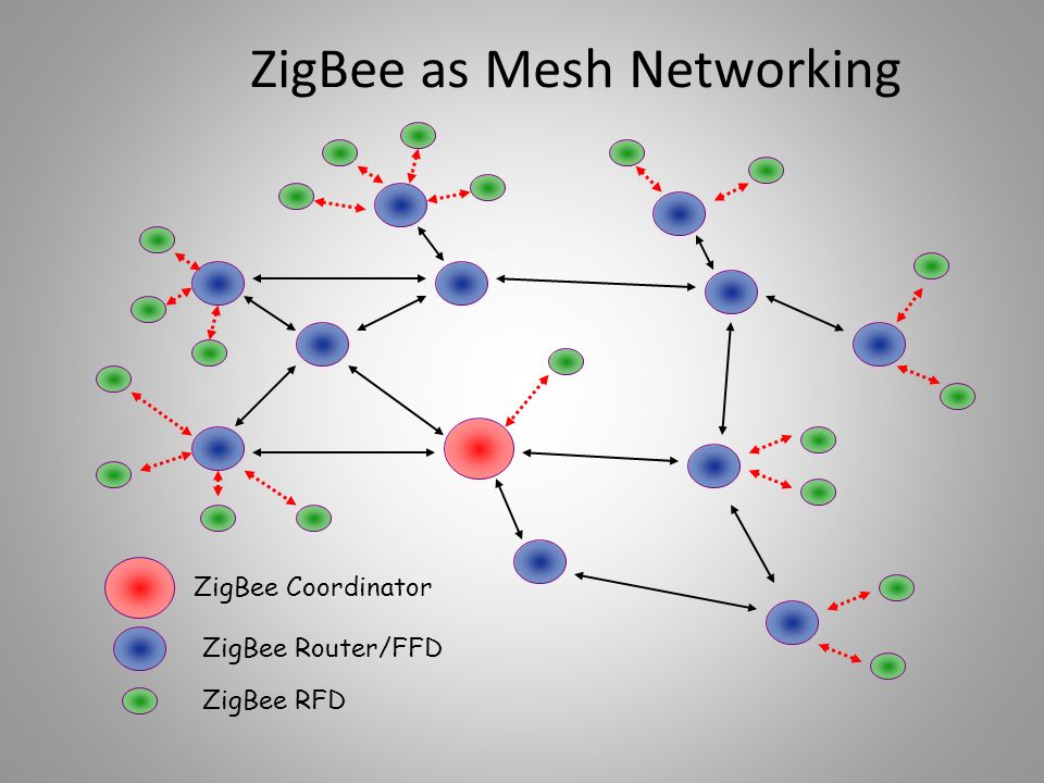 Watchful waiting is an option for people who do not have complications or symptoms with their hernias, and if recommended by their surgeon.
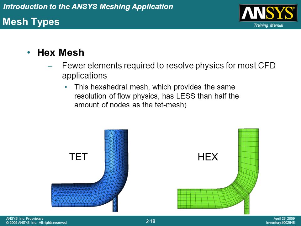 It is designed for long-term use.